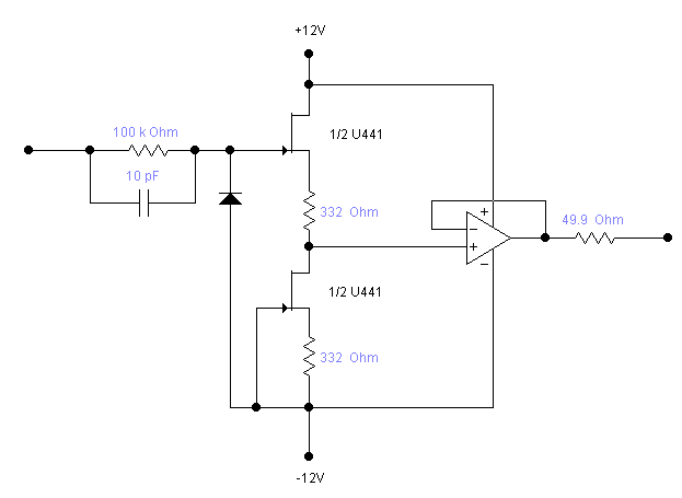
In this forum post http://www.abcelectronique.com/forum/showthread.php?t=35757 one comment explains how a single-ended amplifier works, even providing this diagram:
The key part is a pair of closely matched and coupled N-FET (for temperature compensation). They can be replaced by a pair of BF256 that must be sorted/matched.
This circuit can be duplicated to become a differential amplifier, by also re-wiring the output op-amp (or using an instrumentation amplifier). The differential nature will also compensate for temperature drifts.
From this, 2 things become apparent :
- the symmetric power supply needs to be quite high-voltage so this is a direction for the design of the energy harvester.
- by selecting the proper components, the power consumption can remain within reasonable bounds (with obvious compromises in stability, bandwitdth etc.)
I have seen other, better schematics with higher performance but the cost and complexity become overwhelming. OTOH, a handful of BF256 (VHF N-FET) doesn't cost much.
The supply can be regulated by a couple of micropower LM4041 (initially intended for the ADC of the #Discrete YASEP), drawing only 60µA, capable of up to 10V of shunt (15V abs.max.) and 10mA of sinking. I don't think a scope's probe test point can provide such a current so it's well within the bounds.
Now, it remains to be seen how much the above schematic draws in practice. Linearity, bandwidth (frequency response) etc. are also a concern.
Maybe I'll have to complete my #Quick & Dirty Frequency Generator or buy that DDS from my dear friend noodlehead
 (No, I'm not shooting for GHz precision, my fastest scope reaches 200MHz only)
 Yann Guidon / YGDES
Discussions
Become a Hackaday.io Member
Create an account to leave a comment. Already have an account? Log In.