 Austin Marandos
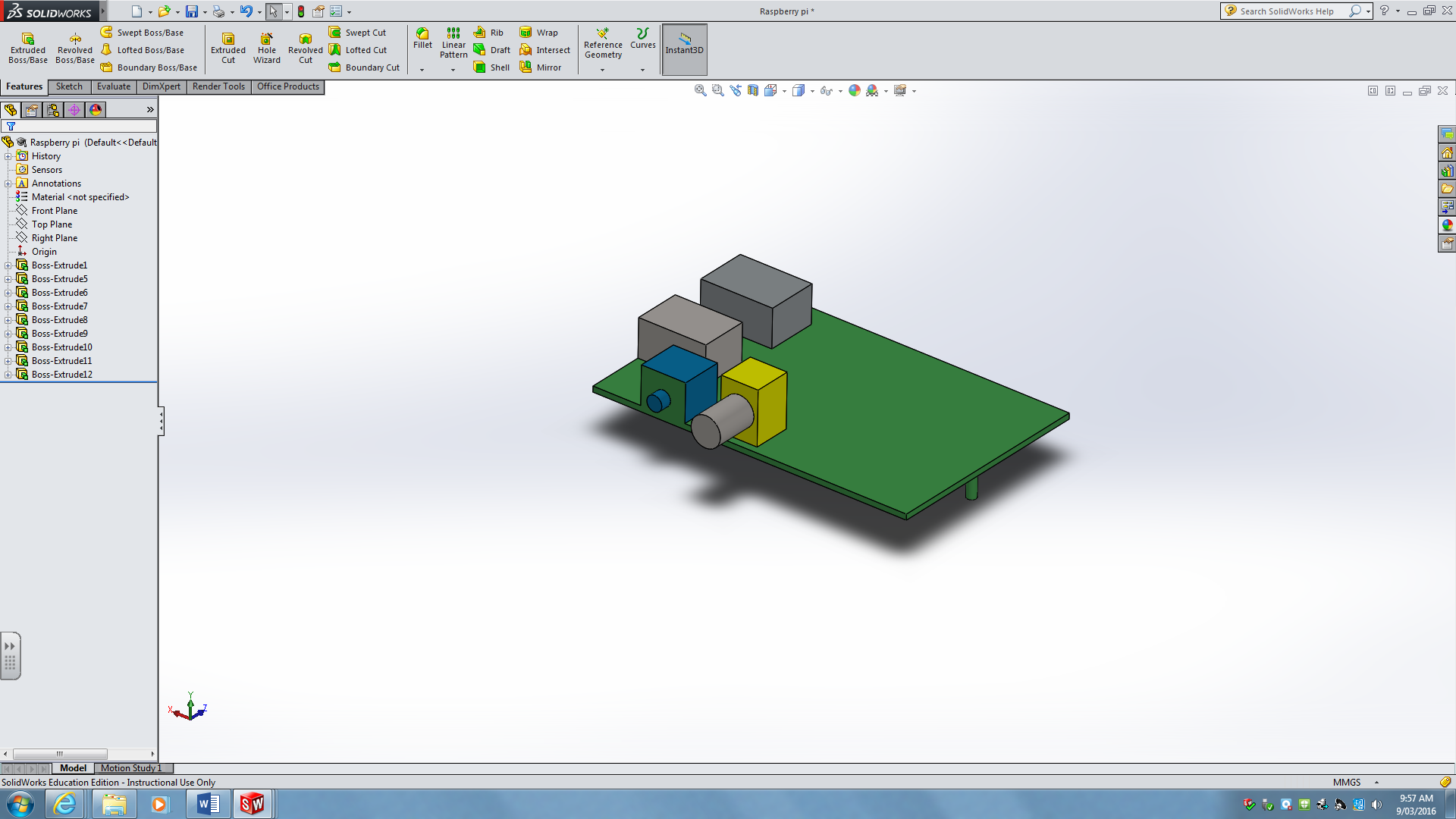
MAIN OBJECTIVE:
To create an open-source programmable and easy to use photo display unit, allowing for an easy transition from digital image to display.
Specific Objectives
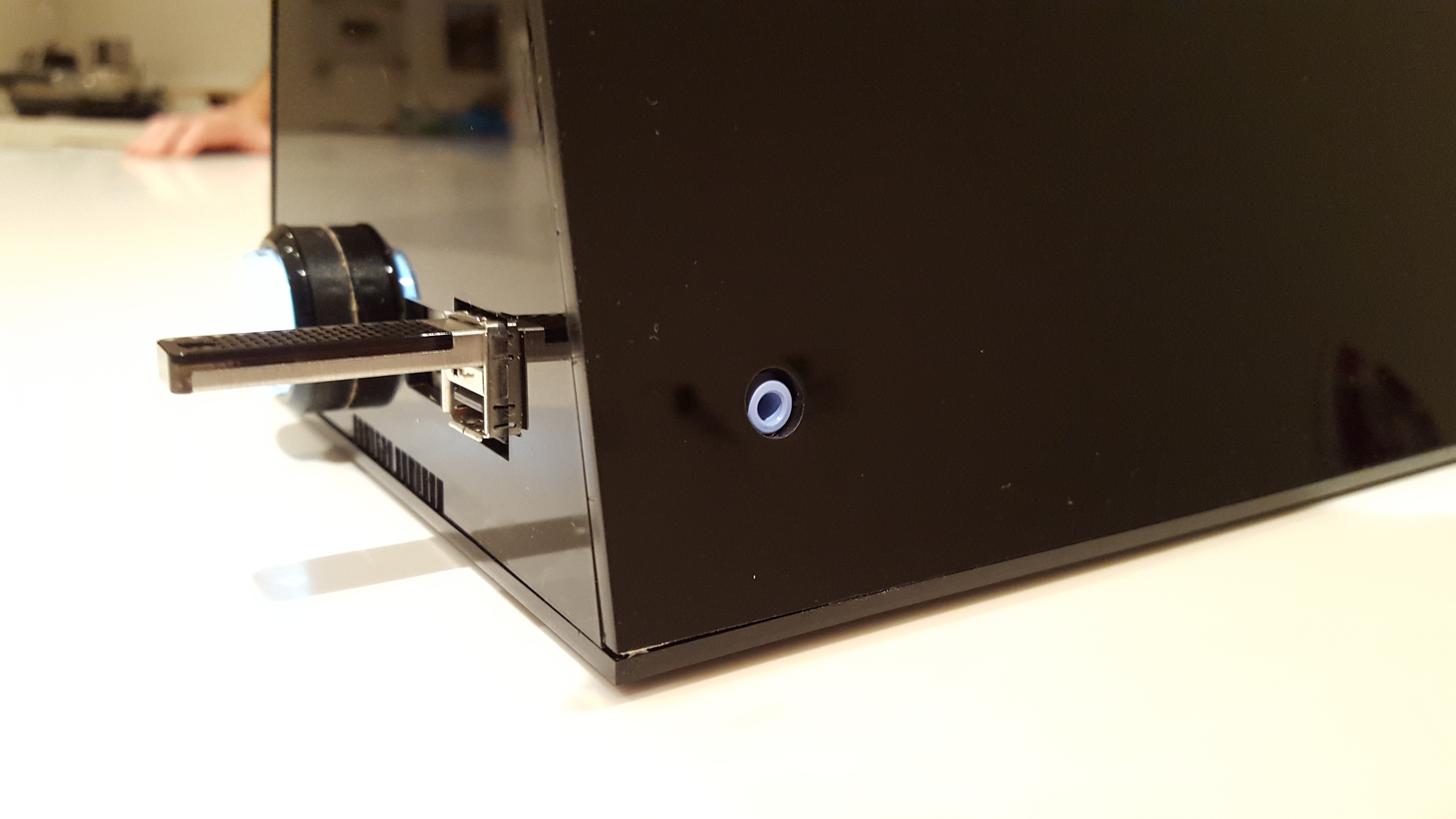
- The unit must Automatically mount the user's USB
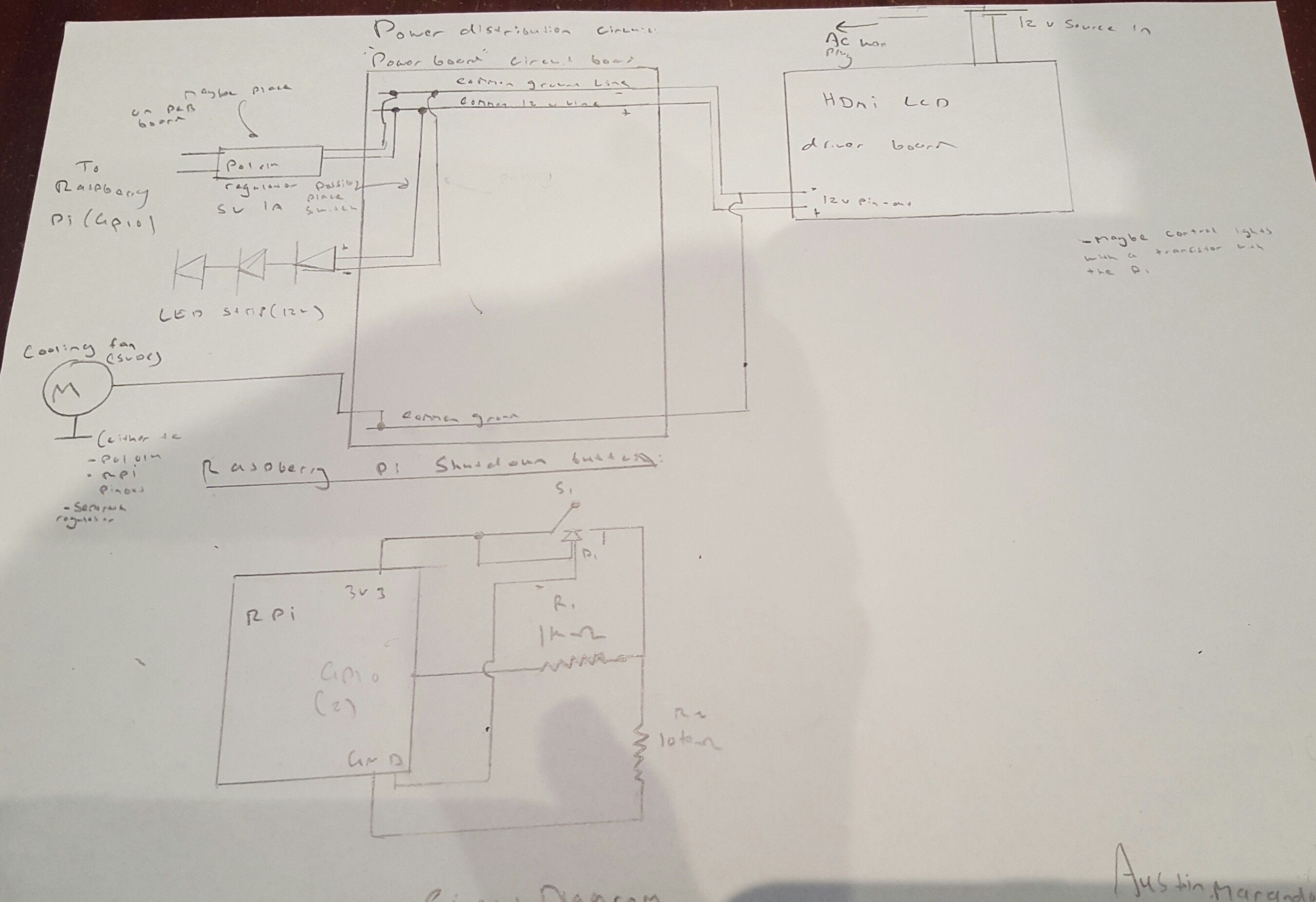
- A Safe shutdown switch
- Must be open-source and allow the user to change anyfeature that he/she desires
- Must be safe to operate, and have adequate cooling systems as to allow for an extended period of operation
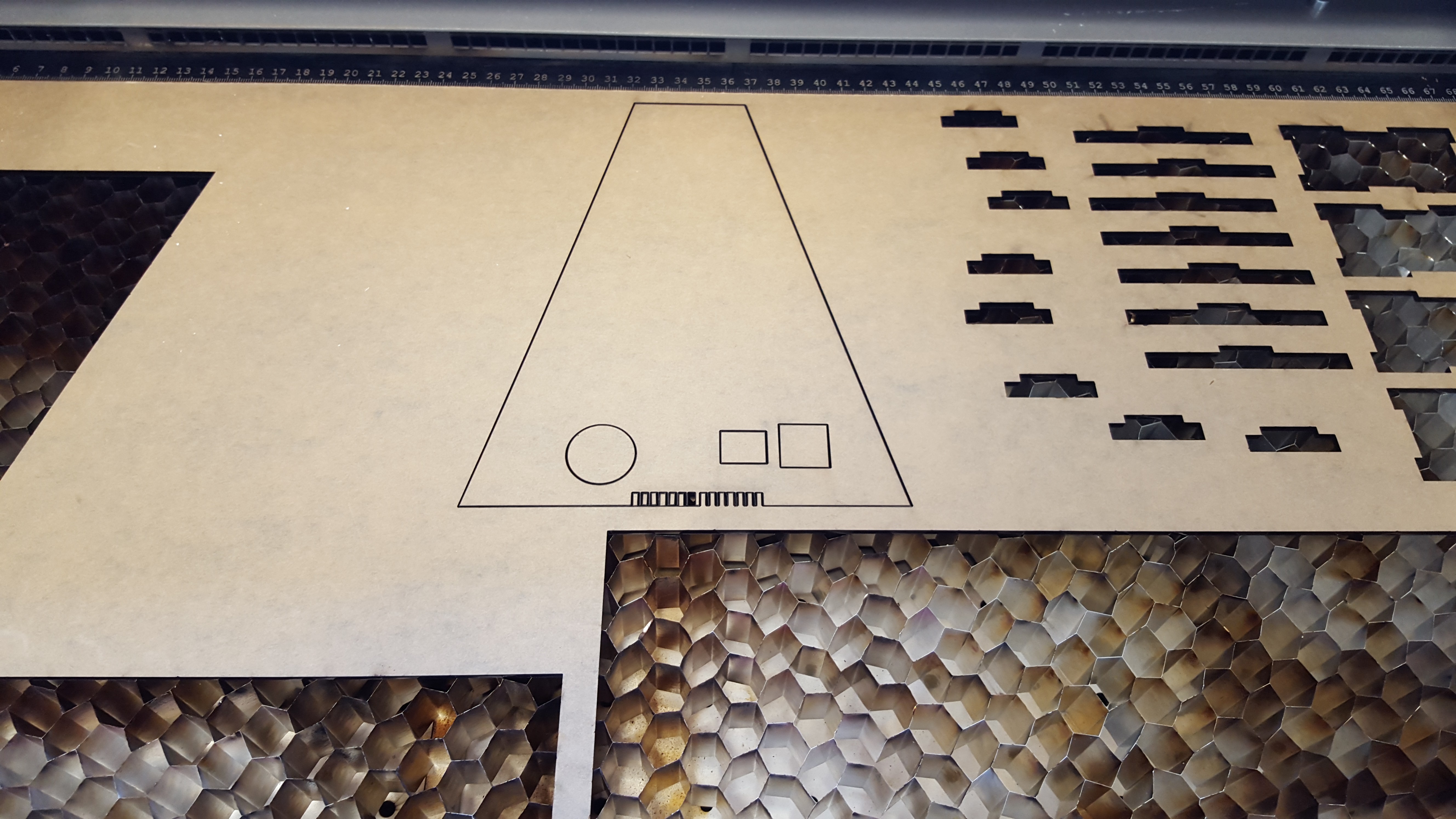
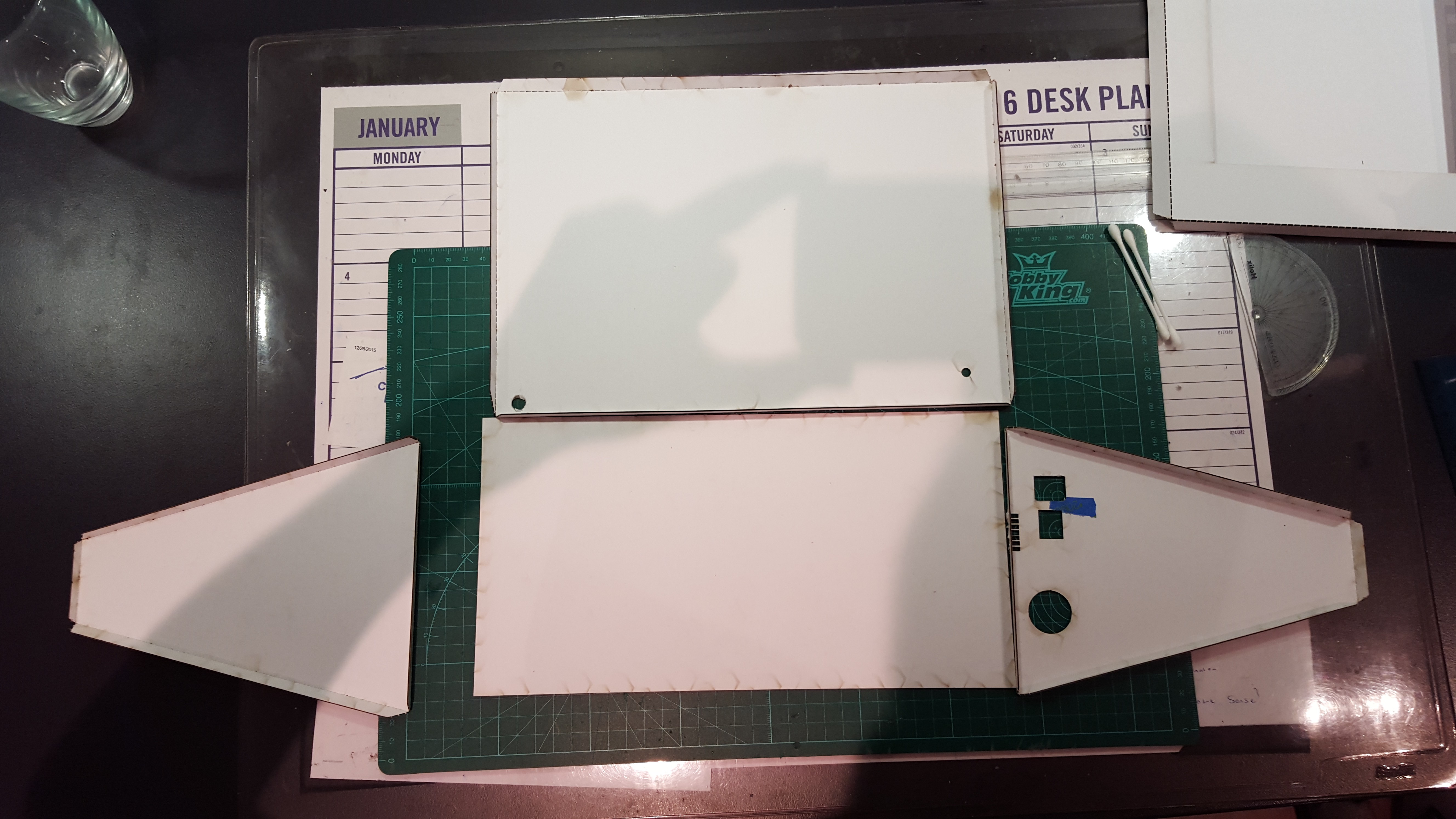
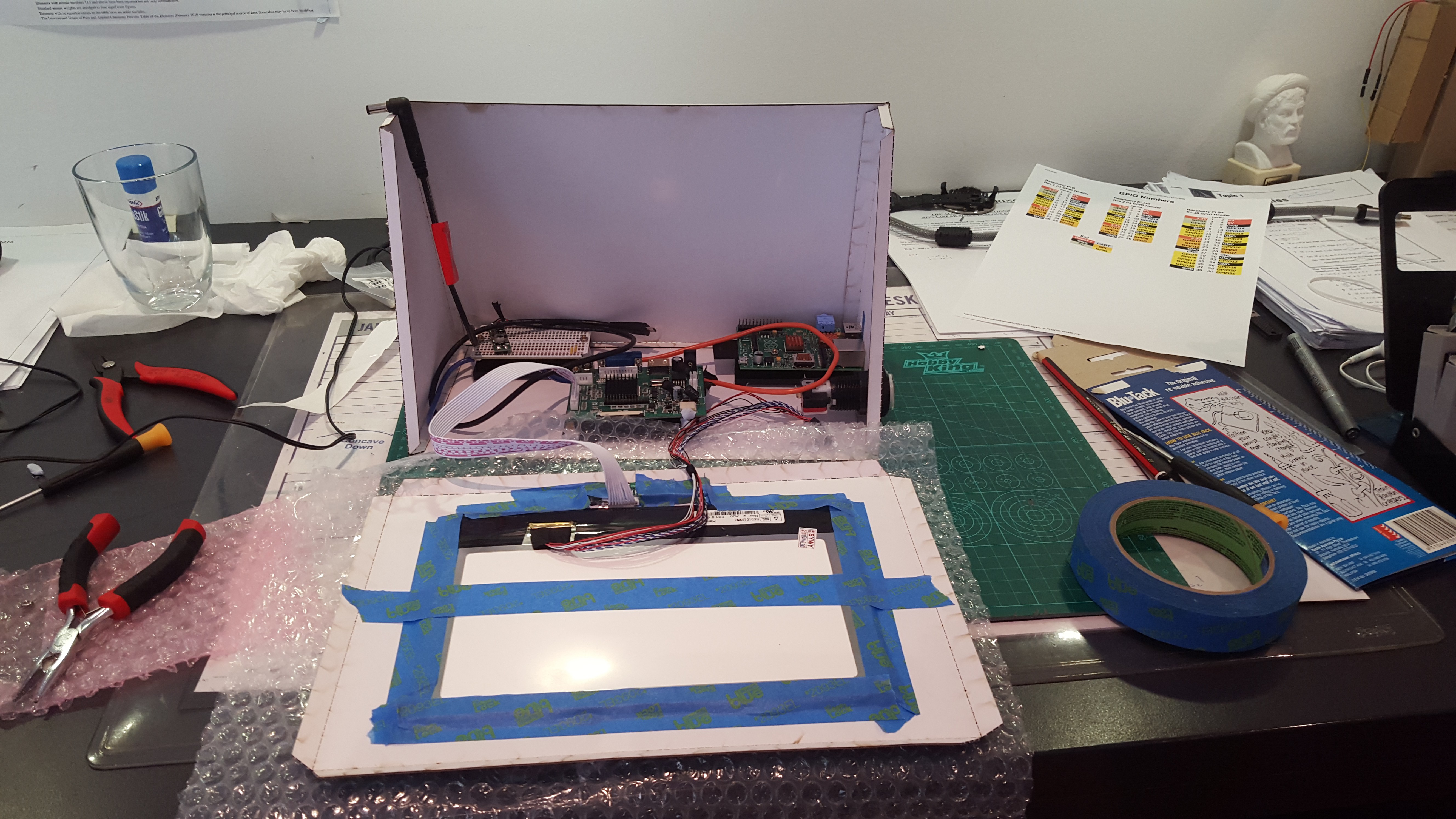
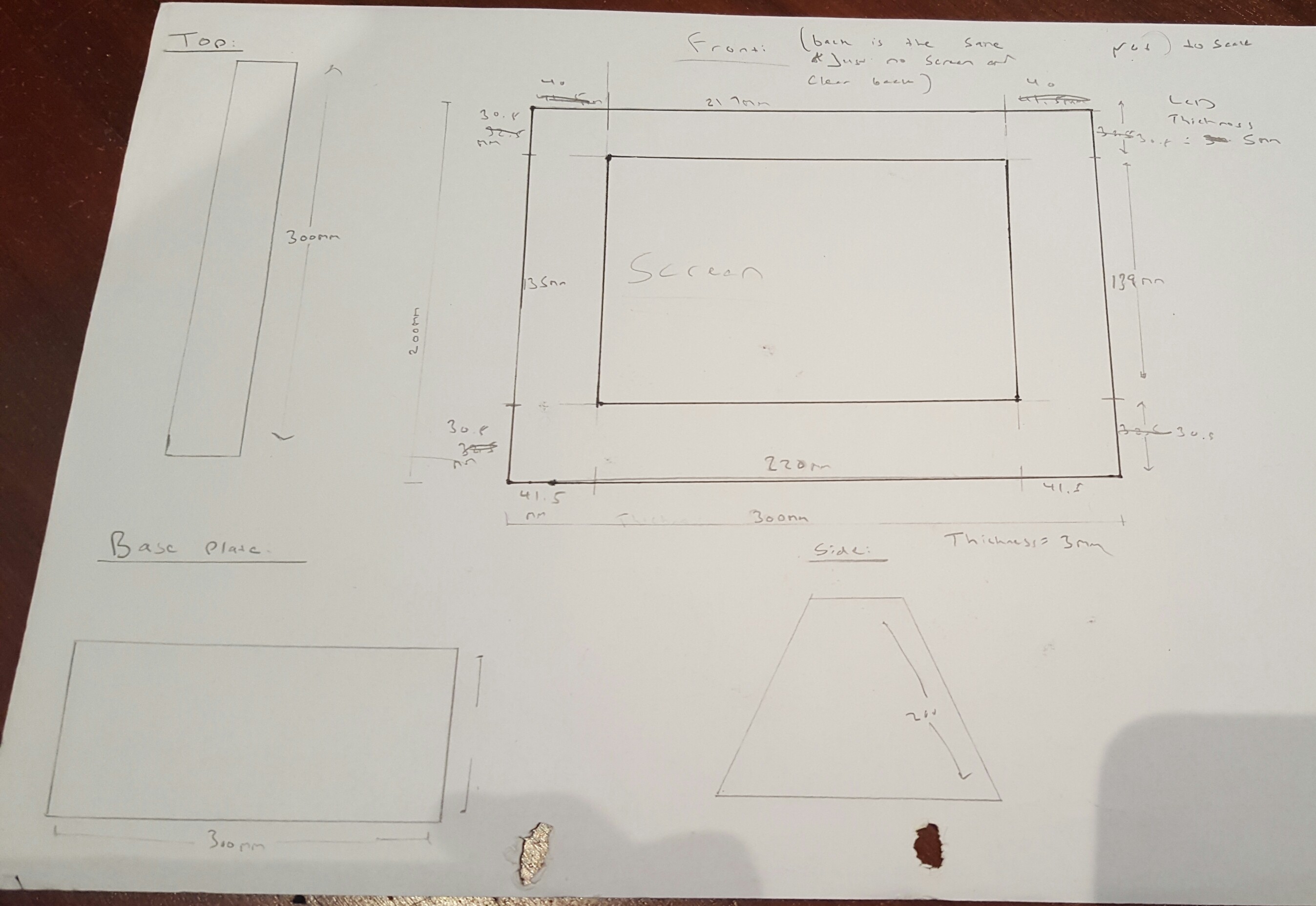
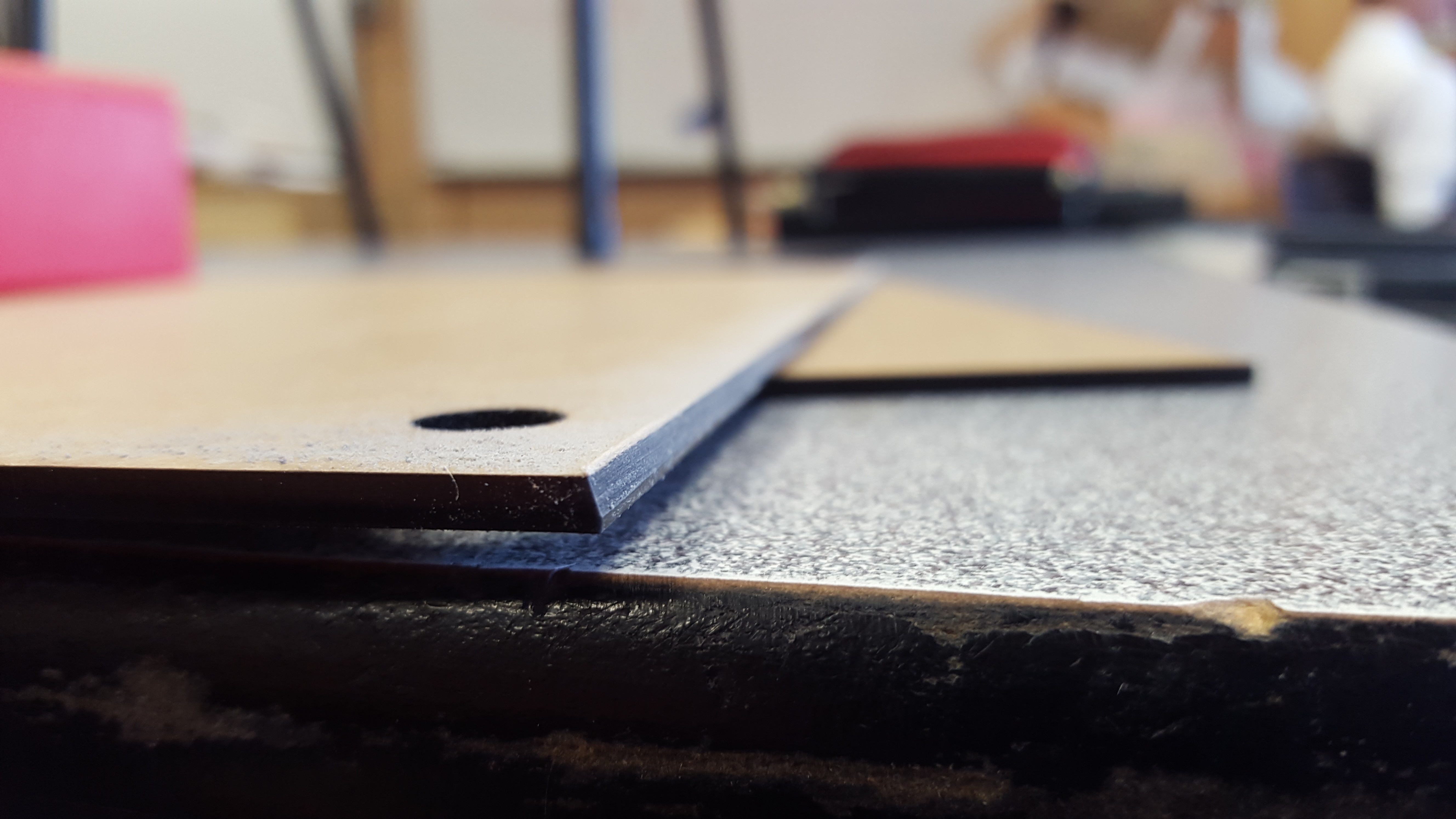 Construction of Perspex pieces:
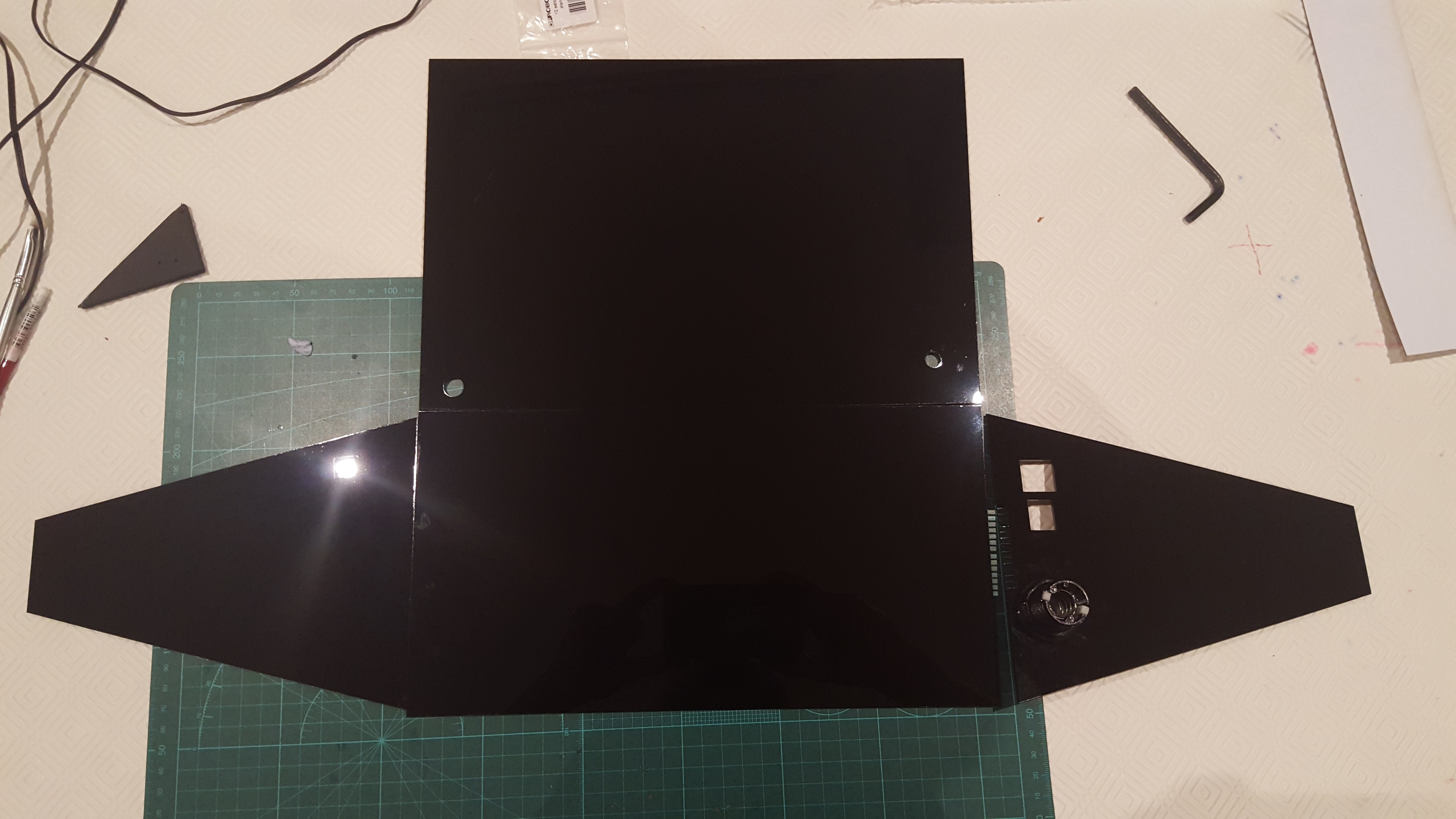 All pieces assembled (with protective cover on). Note: it has not been glued yet since not all the electronics had been installed
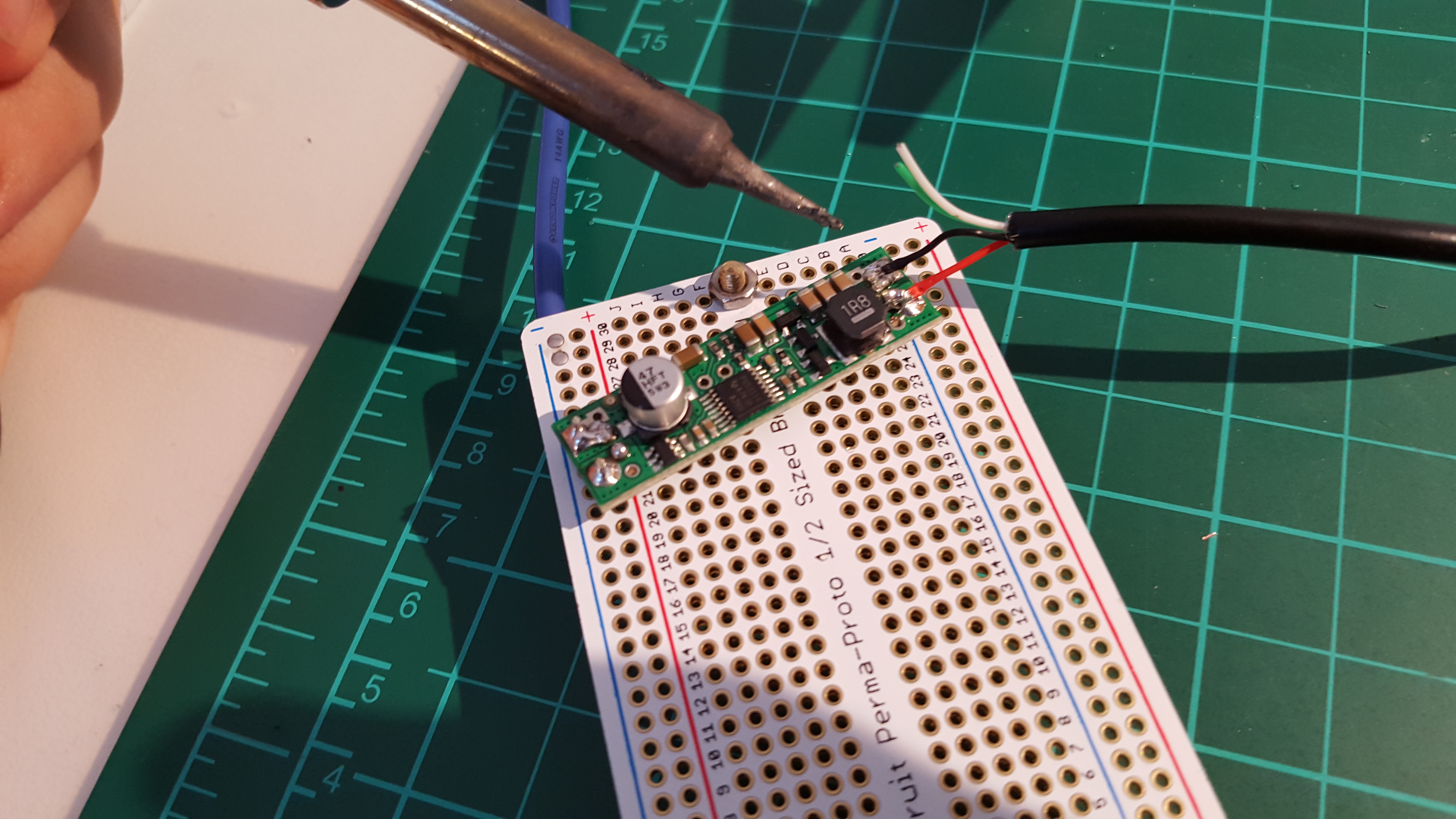
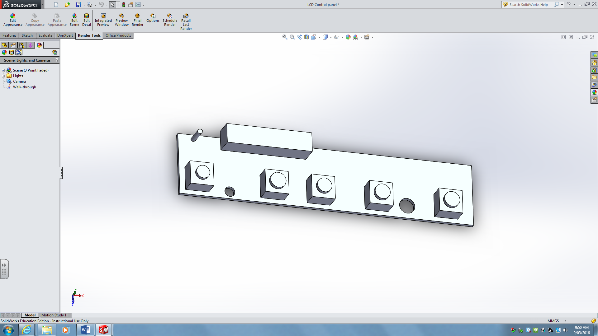
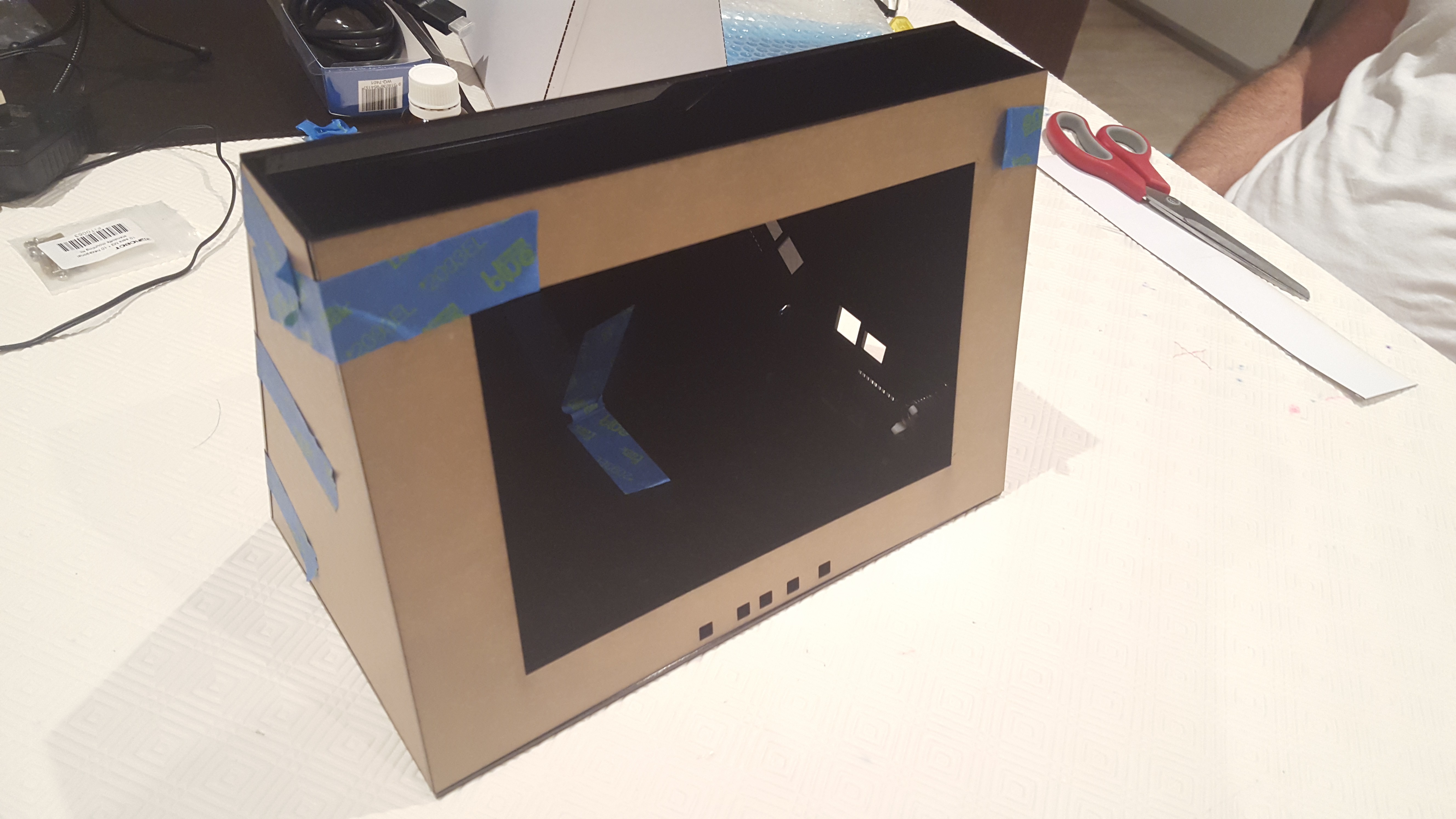 Installation of LCD and Electronics:
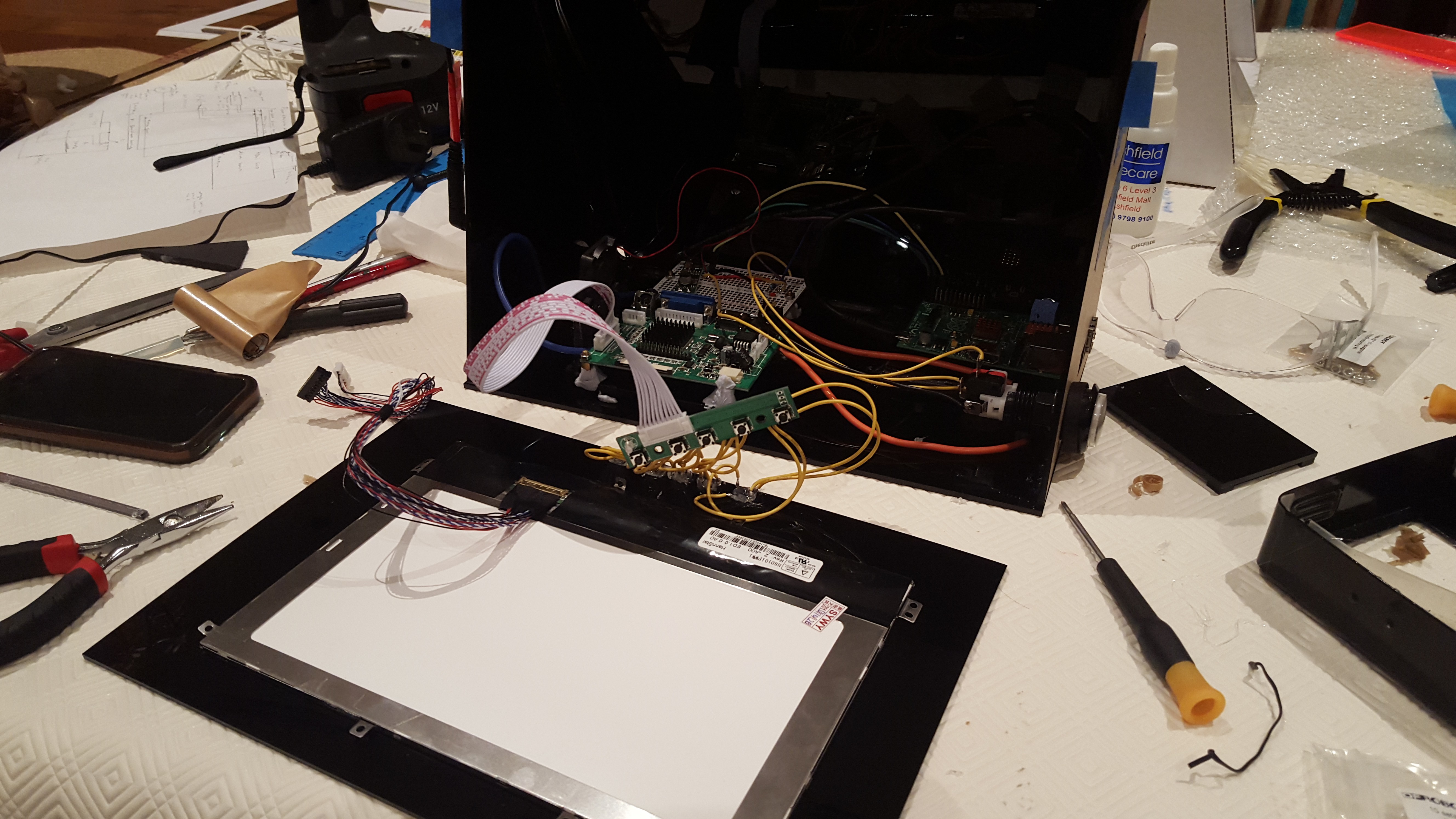 Fan installation: (the fan was pointed directly at the LCD driver IC). There was also a vent on the opposing side.
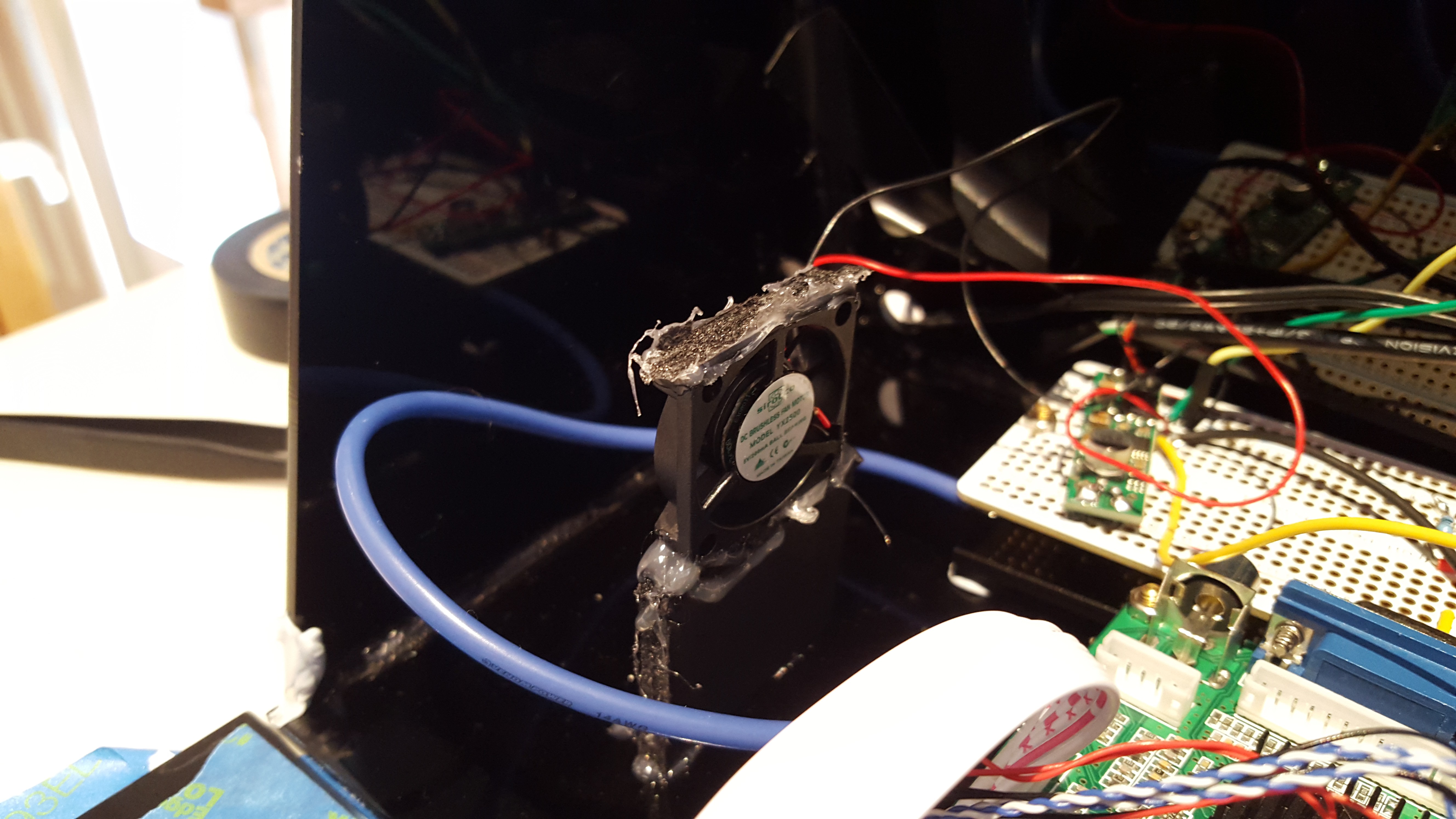
 The top panel had two magnets, this was essential as there was no other way of accessing the electronics.
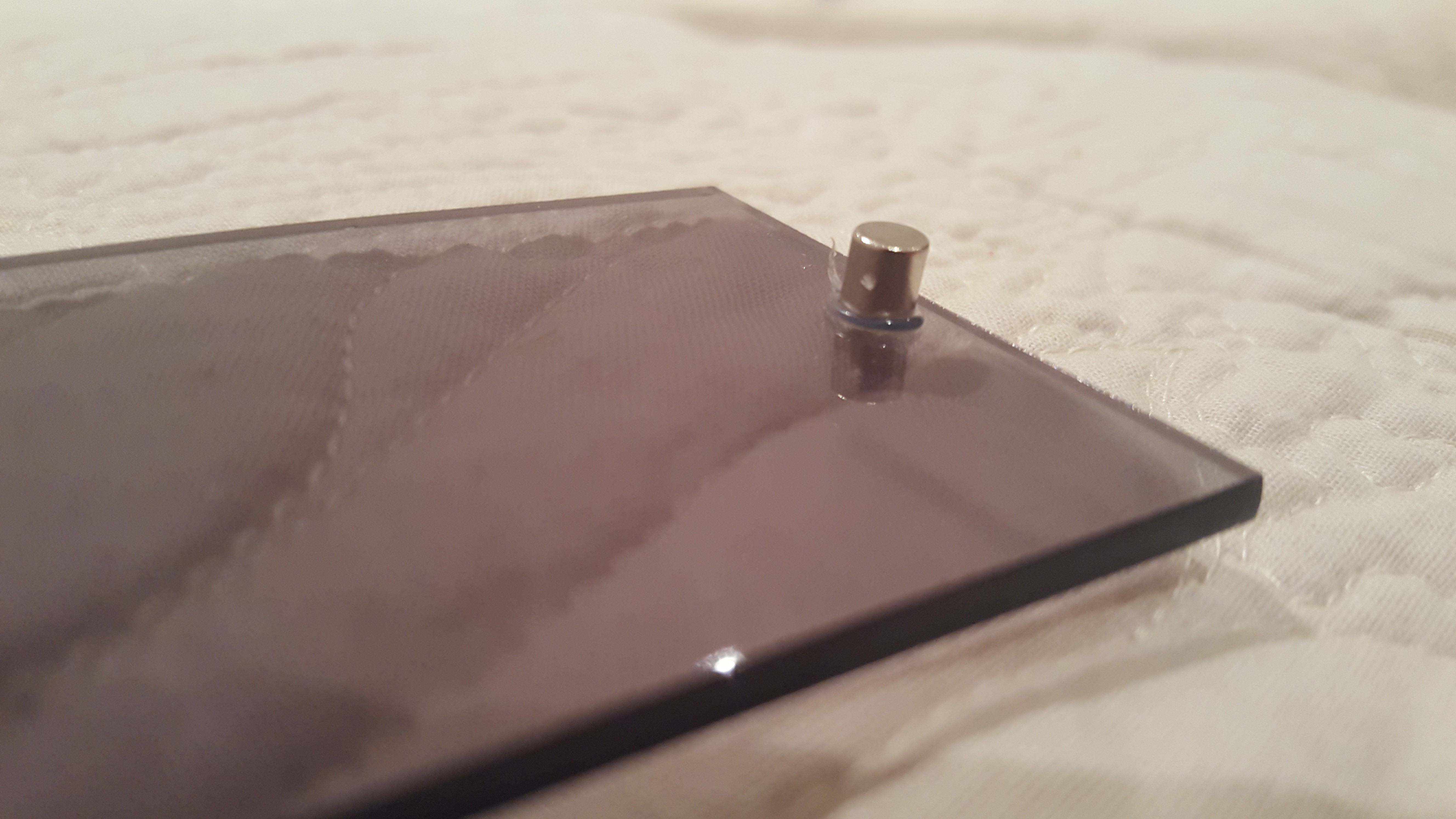 Matching interior magnet:
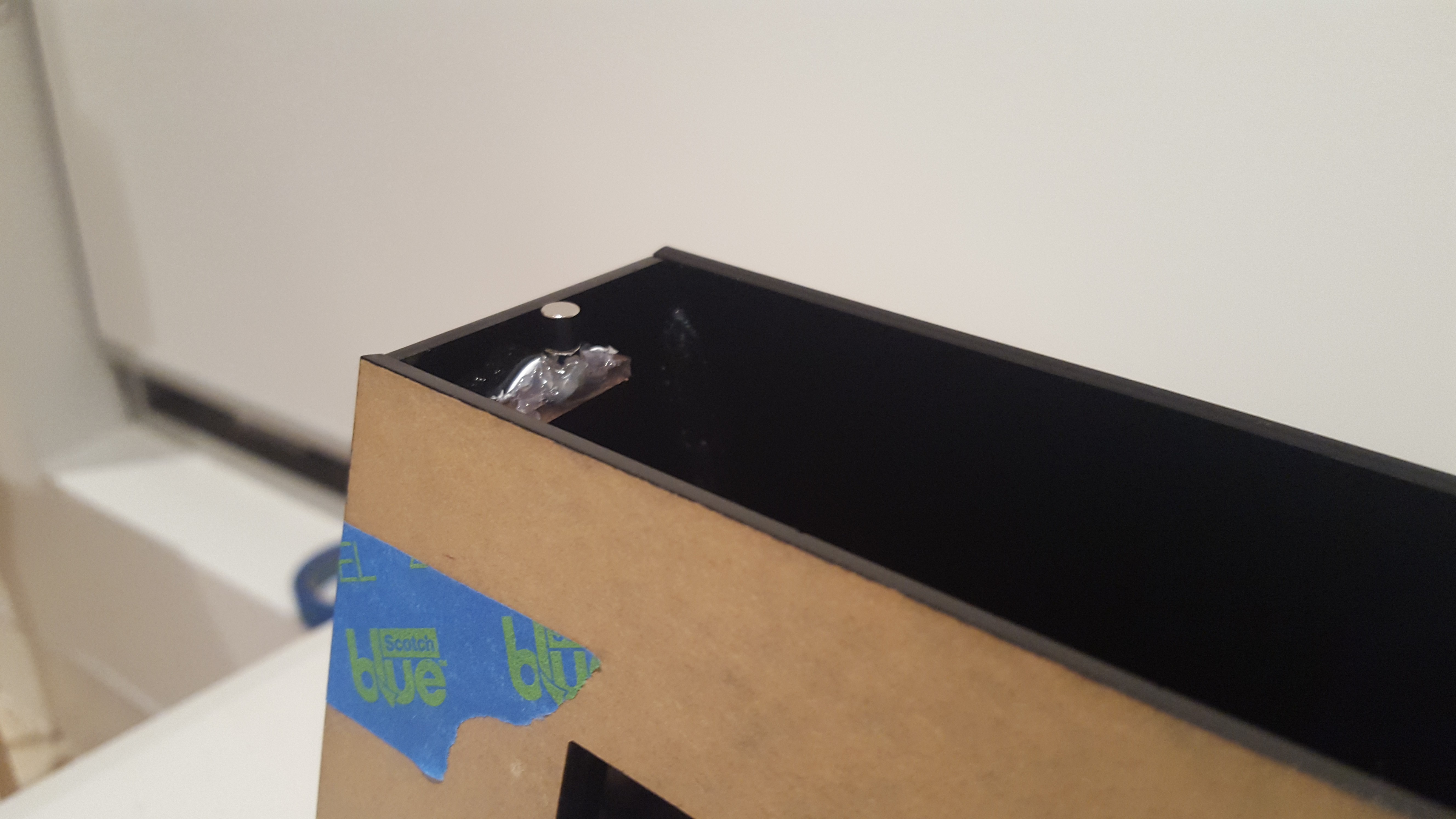 "See through" top panel:
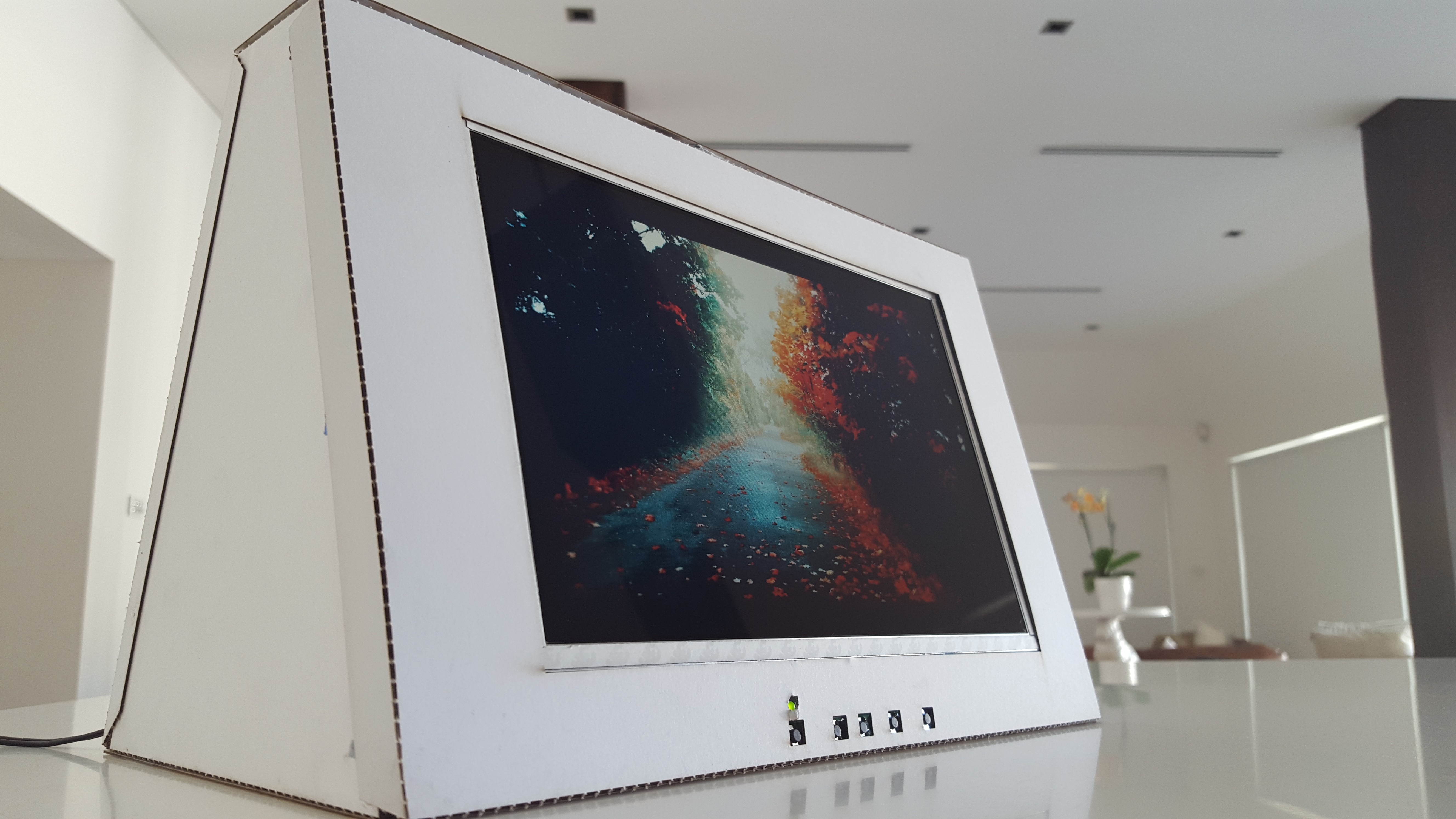
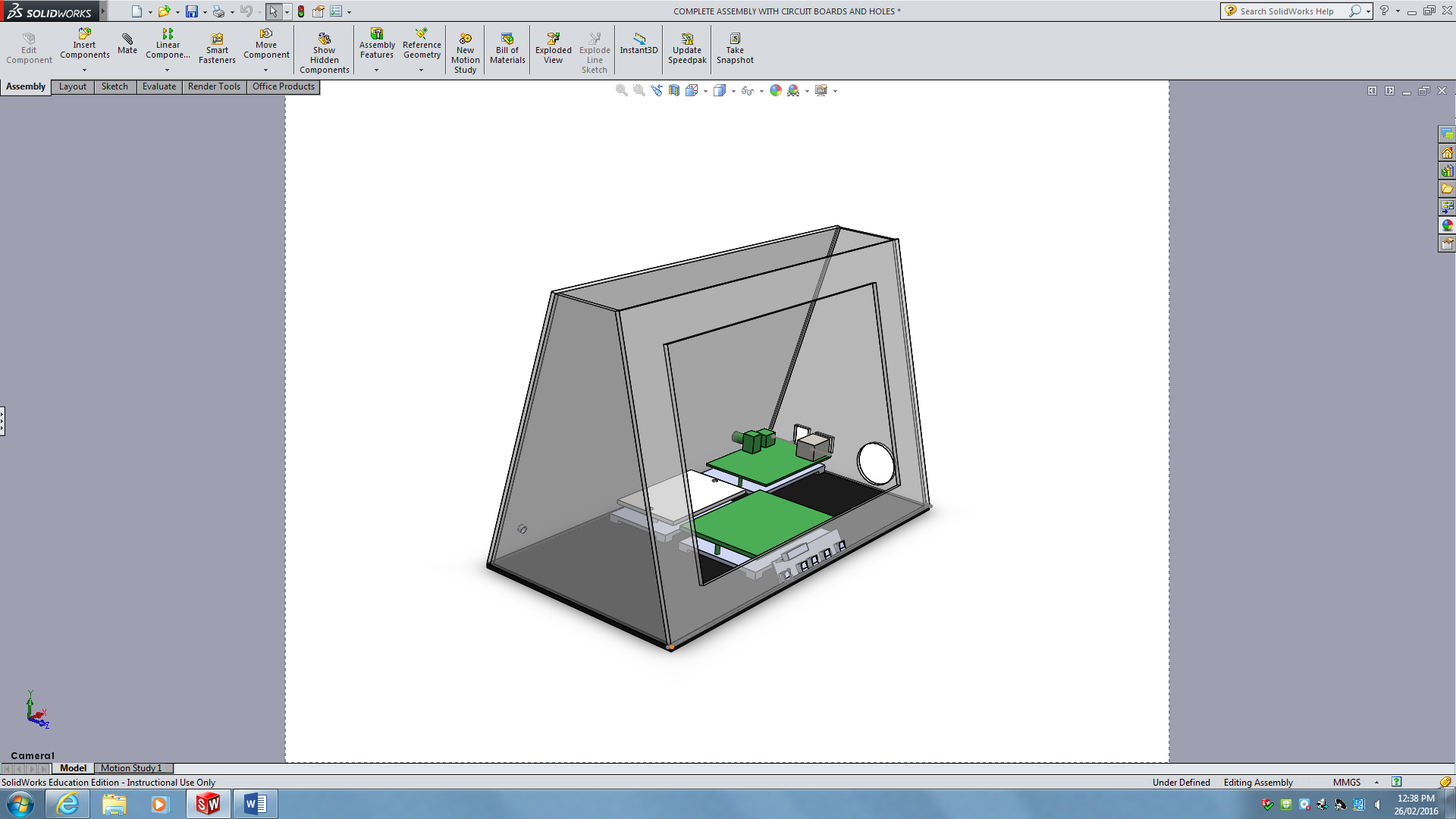
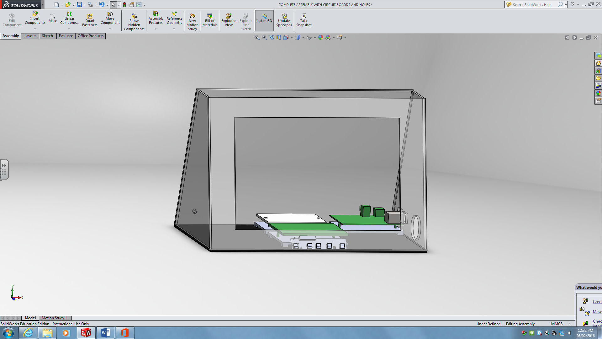
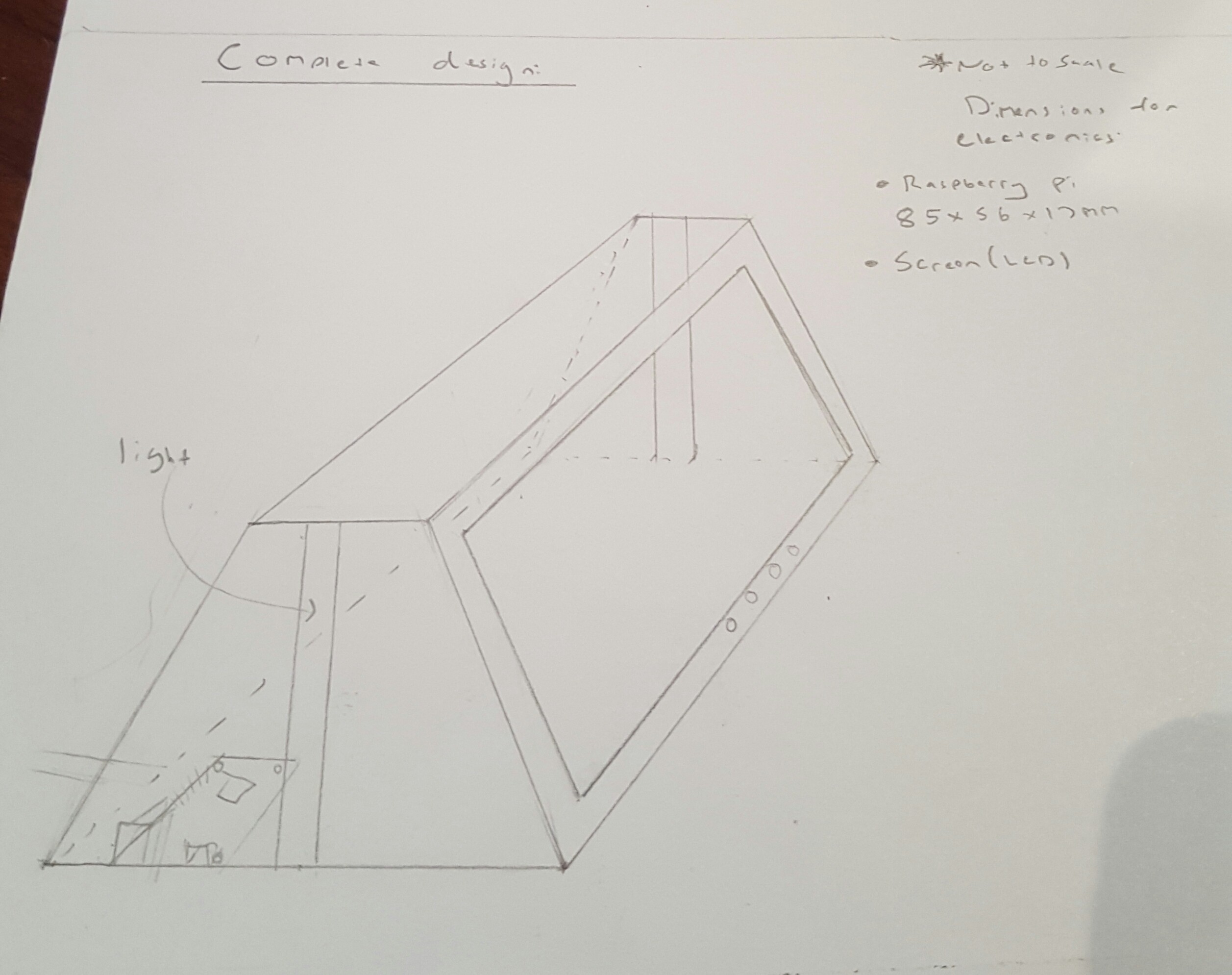
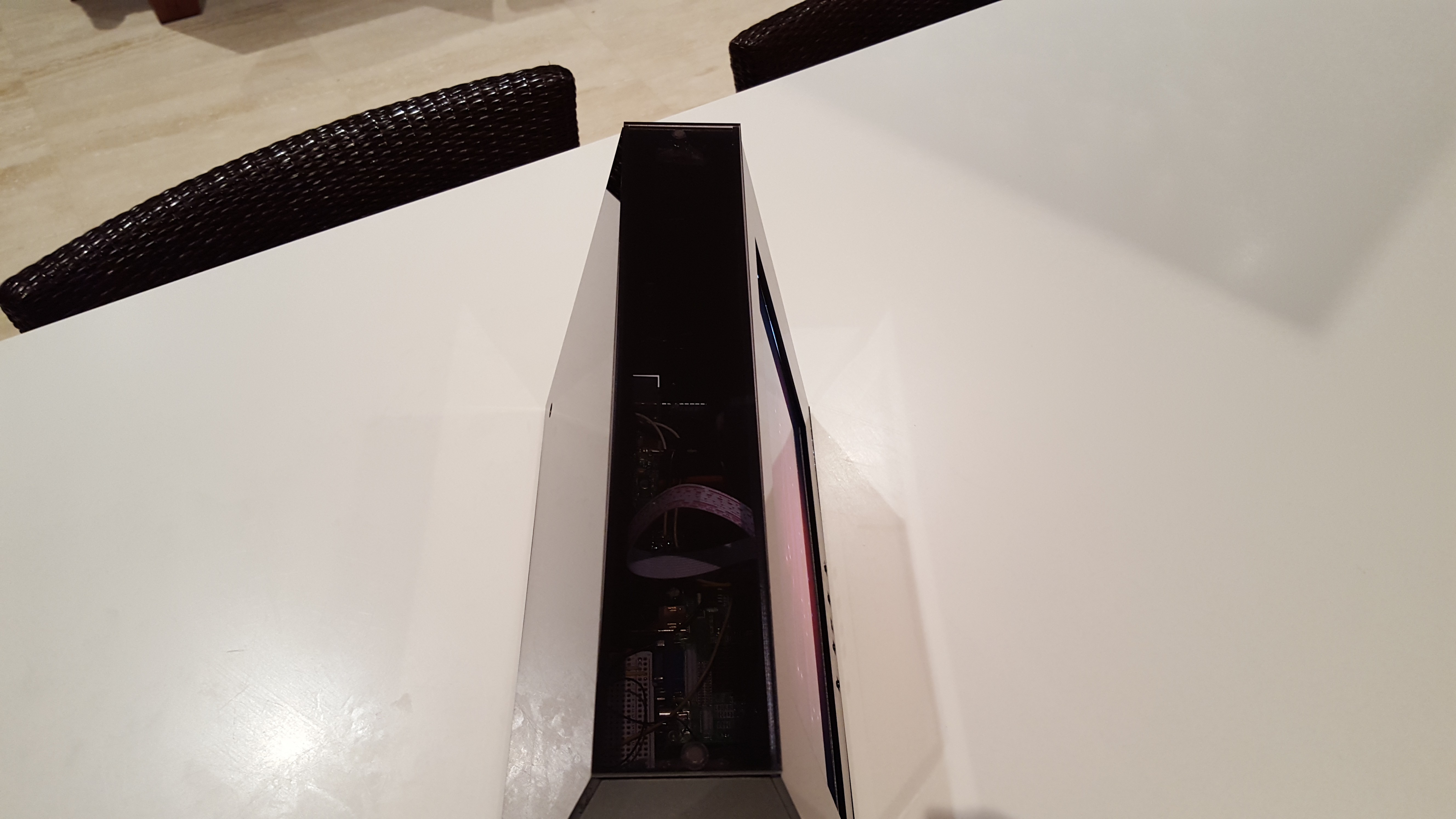 Final design:
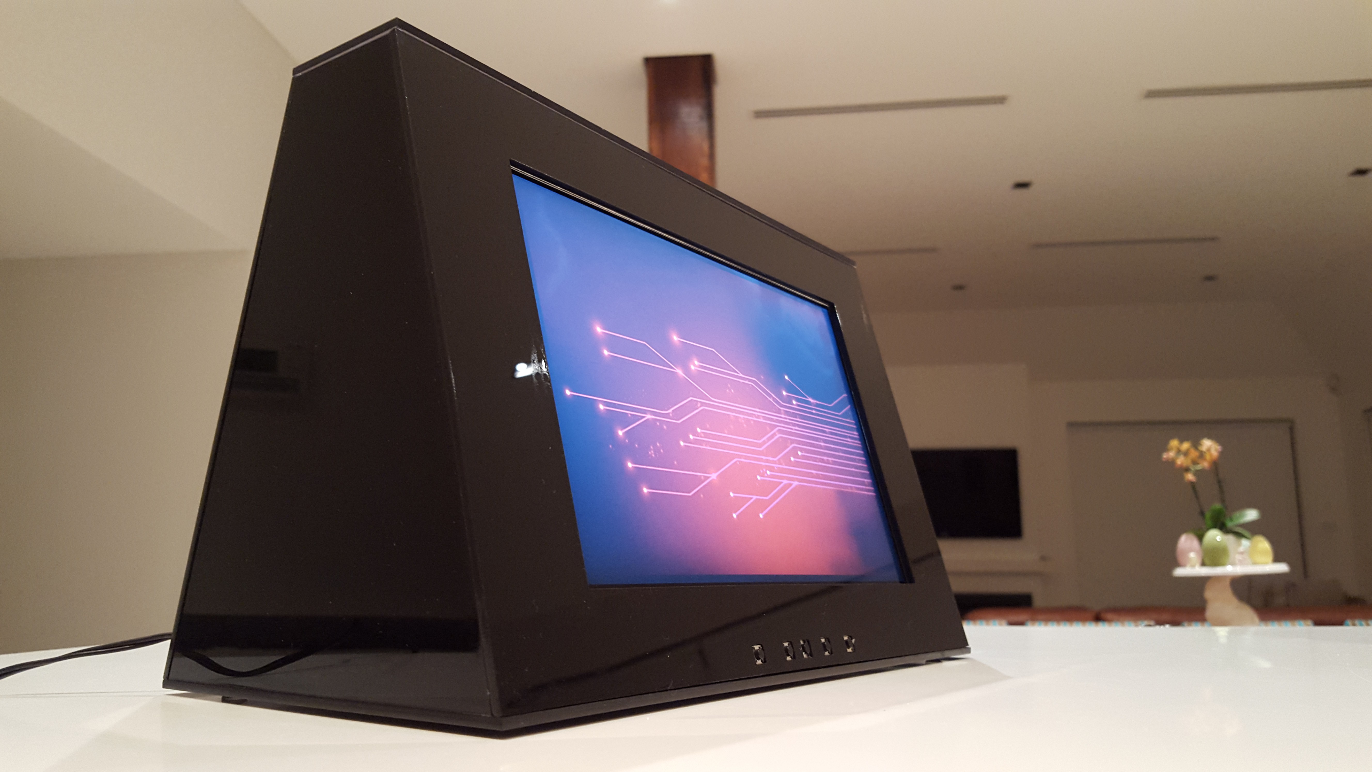
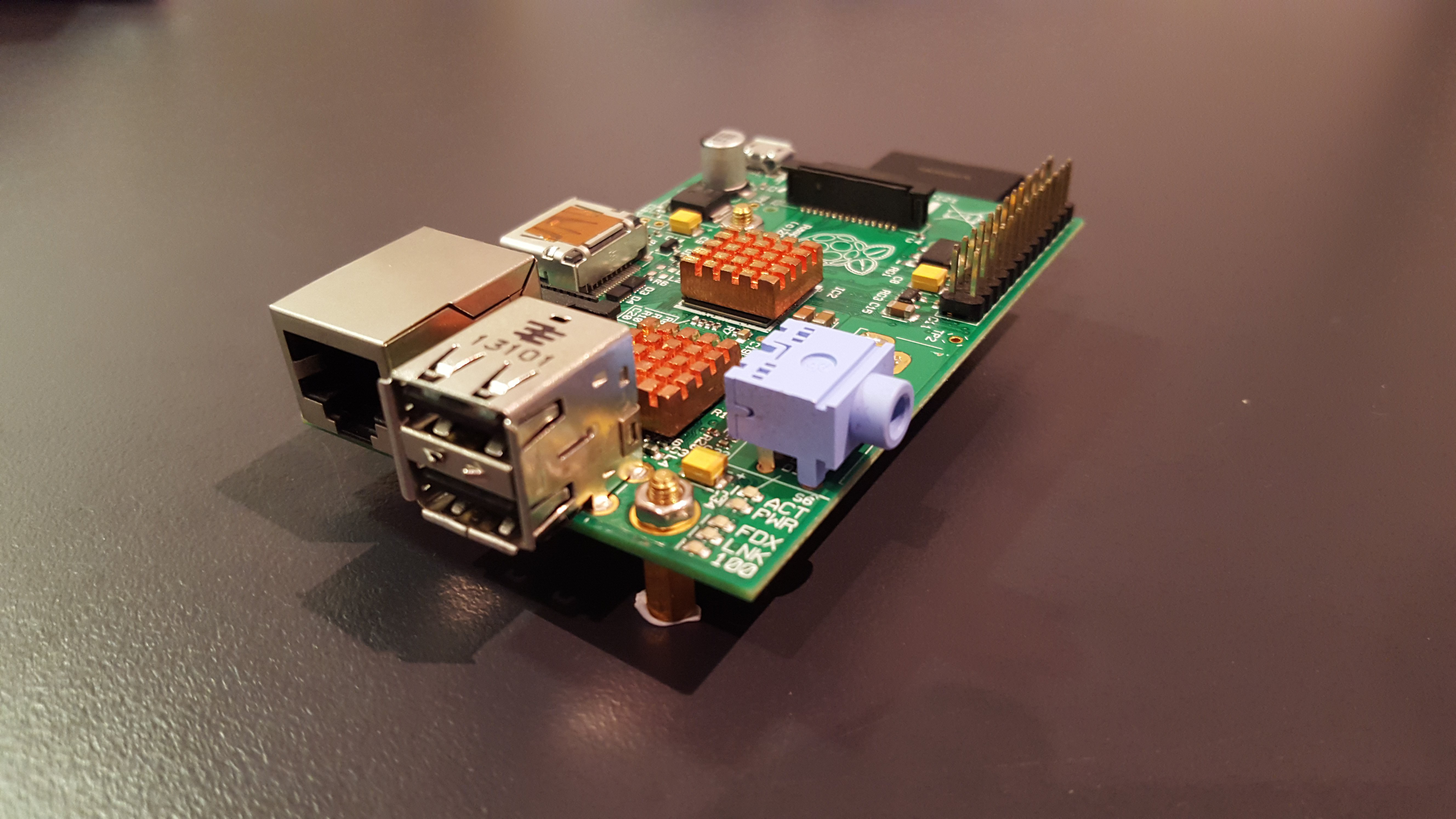
 An finally the 5V micro cooling fan. This thing actually worked wonders, it increased my Pi's performance drastically even though it was located at-least 5cm away from the Pi's CPU
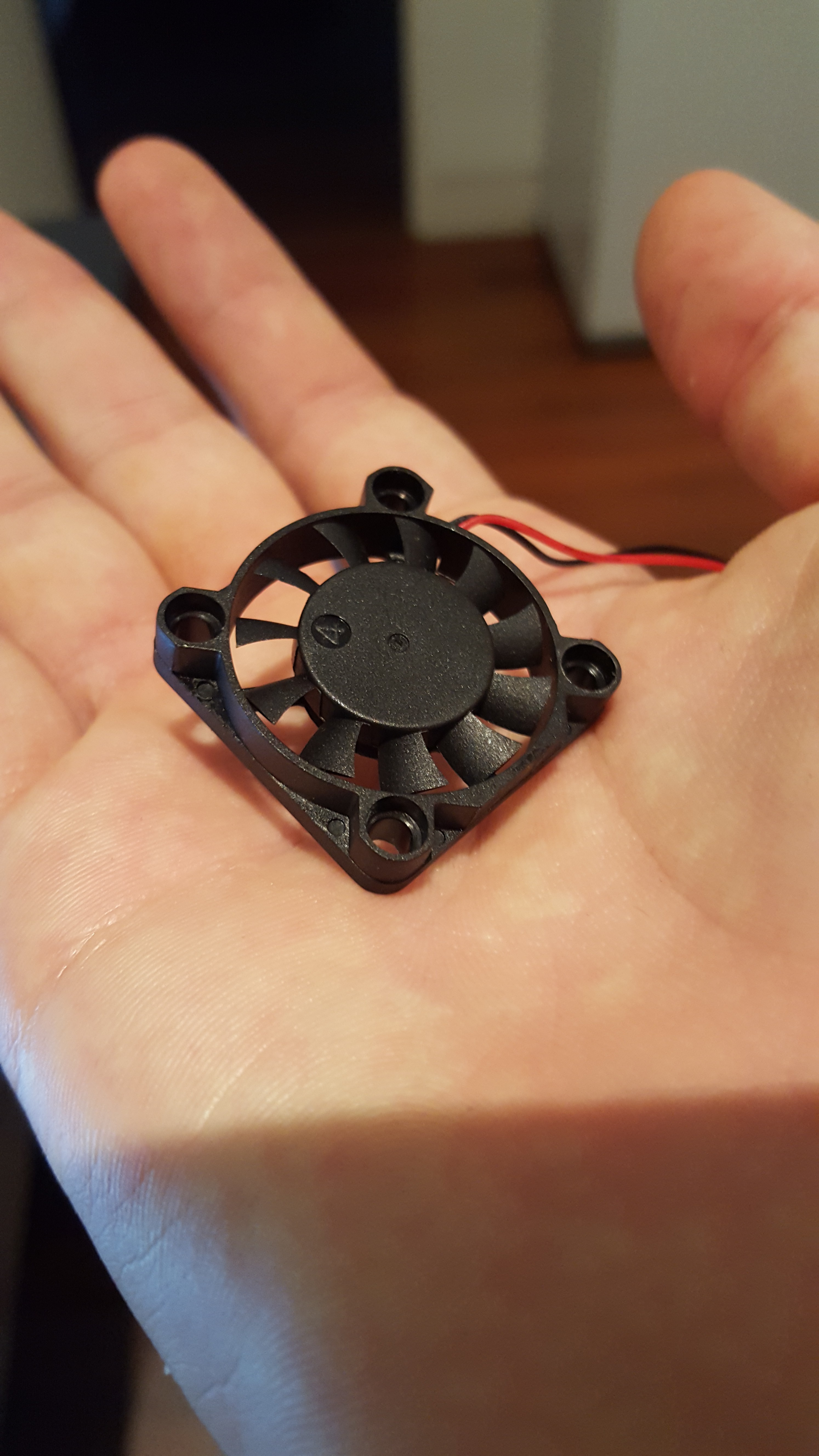

 And more....
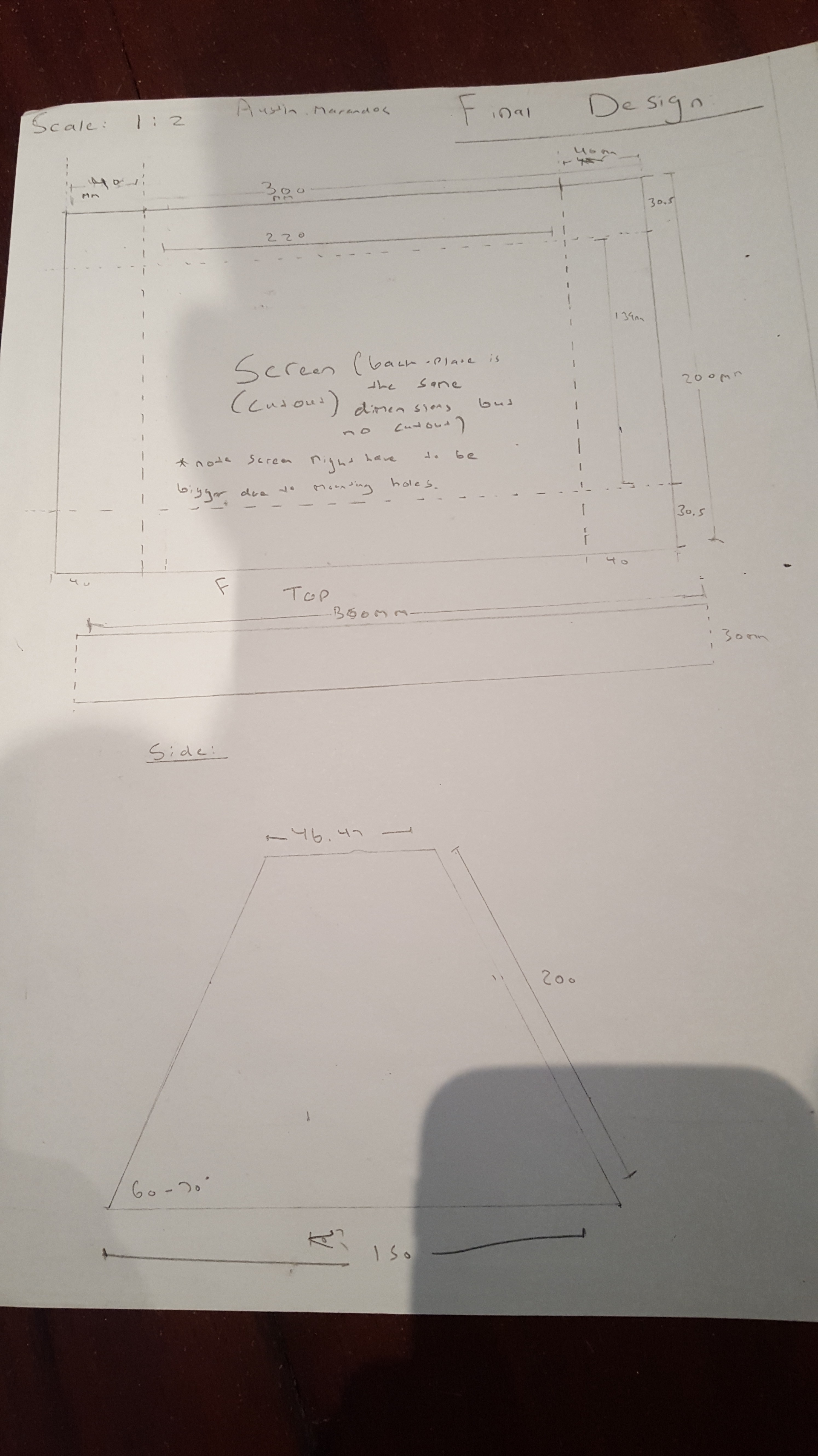
 danielmcgraw
 Cees Meijer
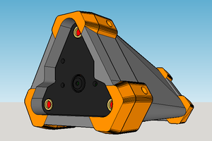
 ken.do
 production