 Tom Meehan
My goal is to develop a Universal Glucose Meter that is:
- Completely open design for hardware and software (all design files, source code, etc. are open).
- That is able to be built from easily sourcable (and inexpensive) components. (Minimal part count).
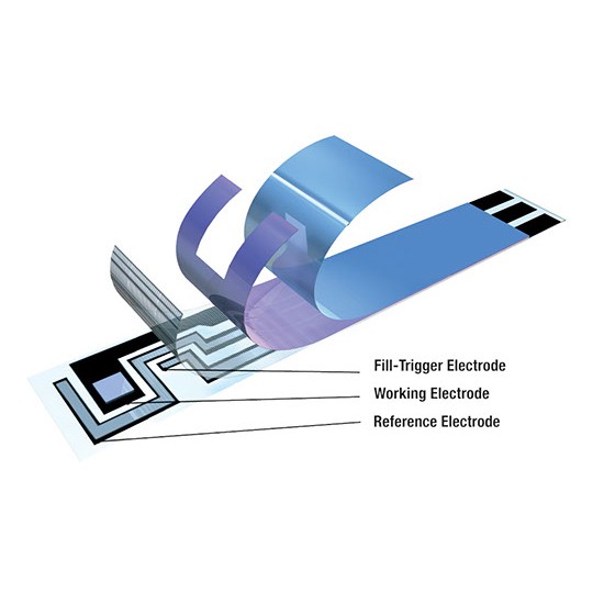
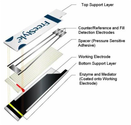
- Is not tied to a single brand of test strips (ideally any brand of strips, but I'll start by focusing on strips that use the Amperometric method for measuring glucose concentrations - since they make up most of the market).
- Ability to select the specific brand and type of strip.
- Ability to calibrate meter to different manufactured lots of test strips using DIY glucose solutions to ensure accuracy and calibration.
- Ability to update firmware to add more strip profiles or additional features.
- Be extensible - act as a platform for others to build on and add features.
- Ultimately I want to help make blood glucose monitoring as accessible and inexpensive as possible.
- Inspire others to develop other open source / open hardware methods of blood glucose measurement that free diabetics from having to buy and use, proprietary, disposable, test-strips.
- This project aims to be a stepping stone toward the development of an inexpensive, open source, method of reliably tracking blood glucose that can, ultimately, improve the lives of the millions of diabetics worldwide.
Quick Links
- Brian Benchoff's article on the Universal Glucometer
- Research References used in this project
- Test Strip Profiles
- Schematics (in the process of updating/revising)/ Eagle Files
- Gerbers (zipped) - (in the process of updating/revising)
- Order Board From OSHPark
- Bill of Materials
- Firmware
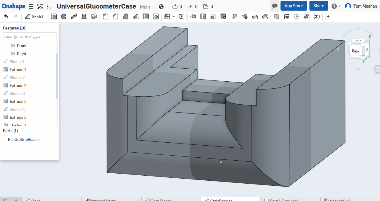
- 3D Print/Design Files
- Open Source License and Open Hardware
Working to complete info in a few links above
Background leading up to project:
My hope was to find a method of measuring blood glucose that didn't require the use of disposable, proprietary test strips. My first thought was to use some measure of light absorbance/transmittance (like with Blood Oxygen saturation) but that turned out to be full of problems from interference with other compounds present in blood. (Check out new findings on this). Then I thought I might be able to use the technology in Continuous Blood Glucose Monitors (CGM's) to make some sort of re-usable sensor - but after a bit of research I found that CGM's rely on the same Glucose Oxidase reaction that is used in test strips and are not able to be reused.
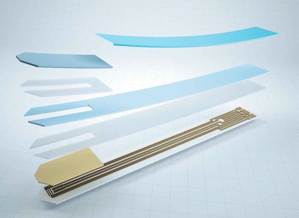
Next, I looked at how current test strips are manufactured, in the hope that their might be a less expensive method of making them. Making test strips, at present, does not seem to be an easy or economical option. Next, I looked for a method that could use a washable (cleanable) and reusable sensor (nothing to throw away). Again, this proved to be difficult to implement outside a laboratory setting. Other technologies: carbon nanotubes, quantum cascade lasers, dielectric spectroscopy, etc. are beyond my knowledge base (at the present time - but hopefully not forever).
Currently the best strategy seems to be to build a meter that is able to utilize multiple brands of strips and can be calibrated using a standardized glucose solutions.
Strips are by far the biggest expense in monitoring glucose levels. So, being able to purchase strips that are lower cost or discounted (on sale) without the need to actually purchase a new meter - could, hopefully, provide significant savings to patients. While it is possible to get meters cheap or even free (right now you need a prescription for a particular meter to get it free) no one wants to keep track of 4, 5 or more meters just to be able to take advantage of sales or discounts on strips.
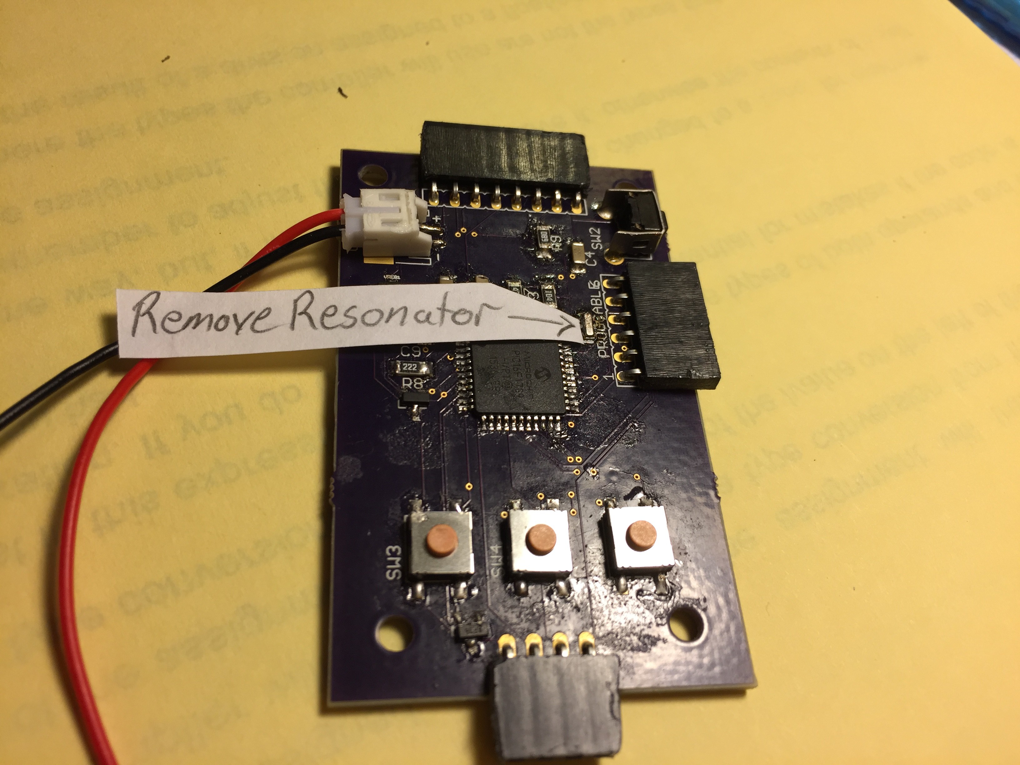
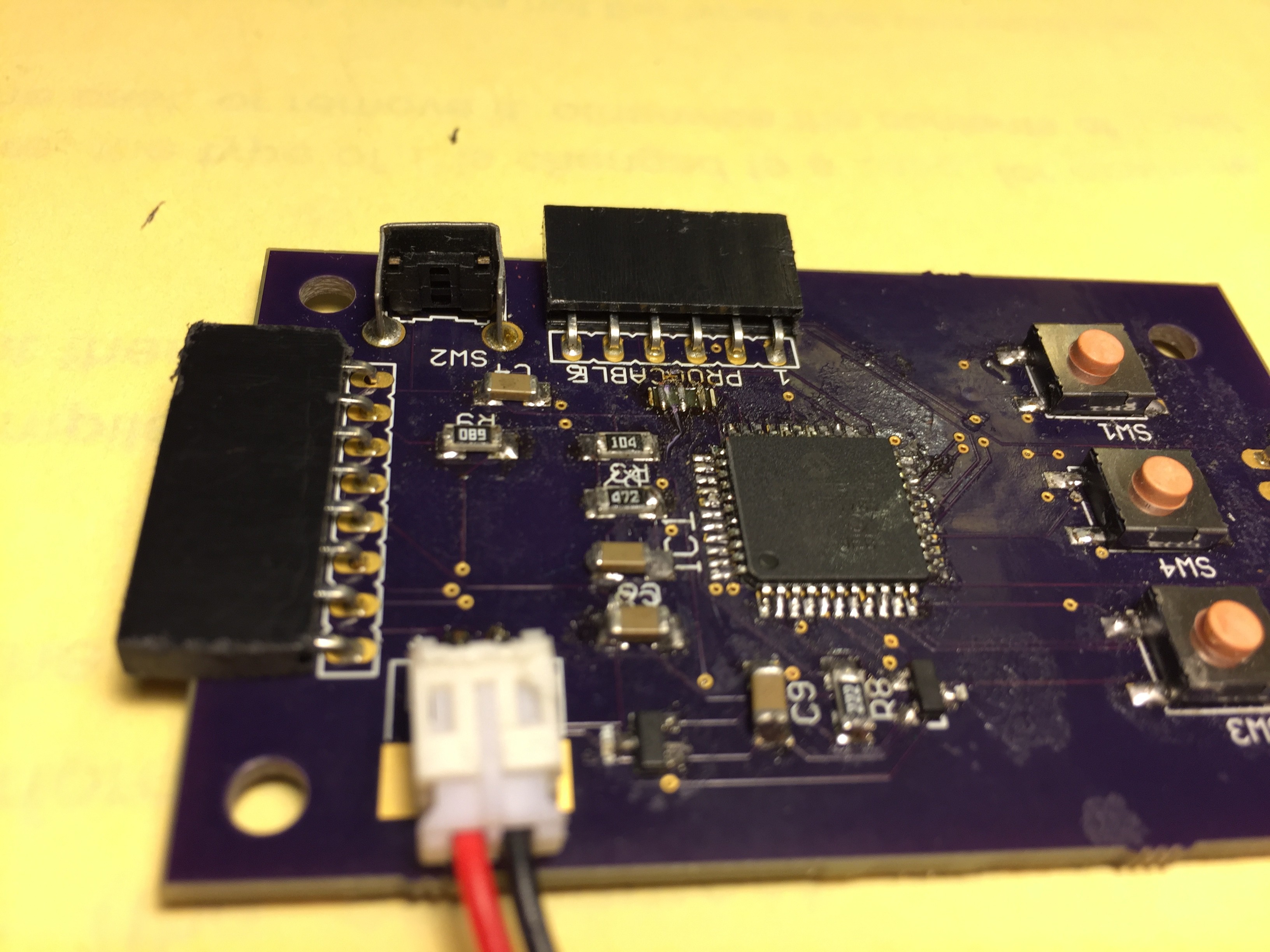
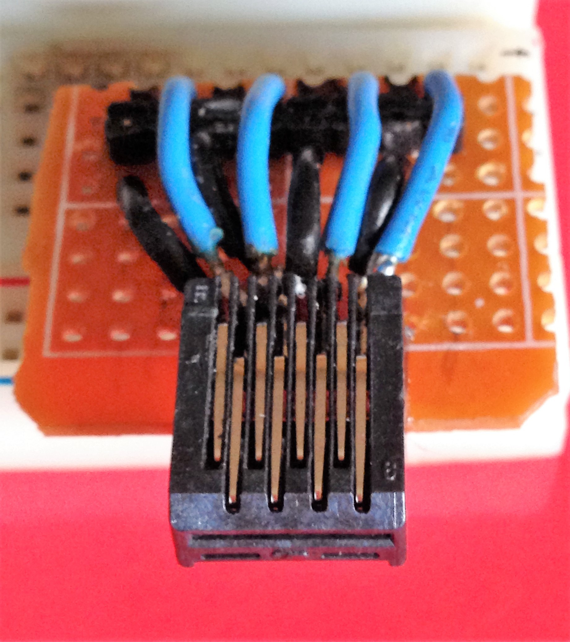
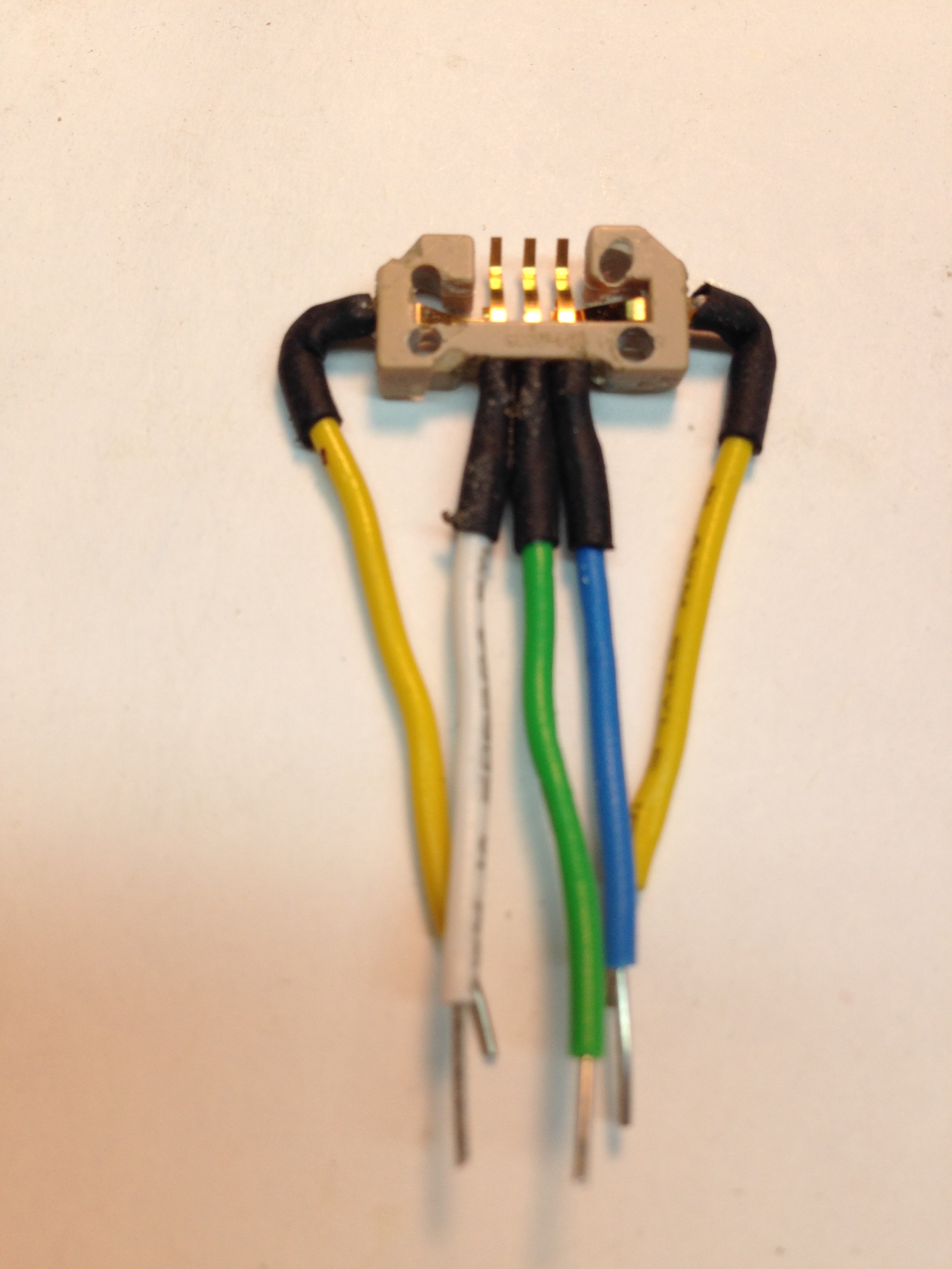
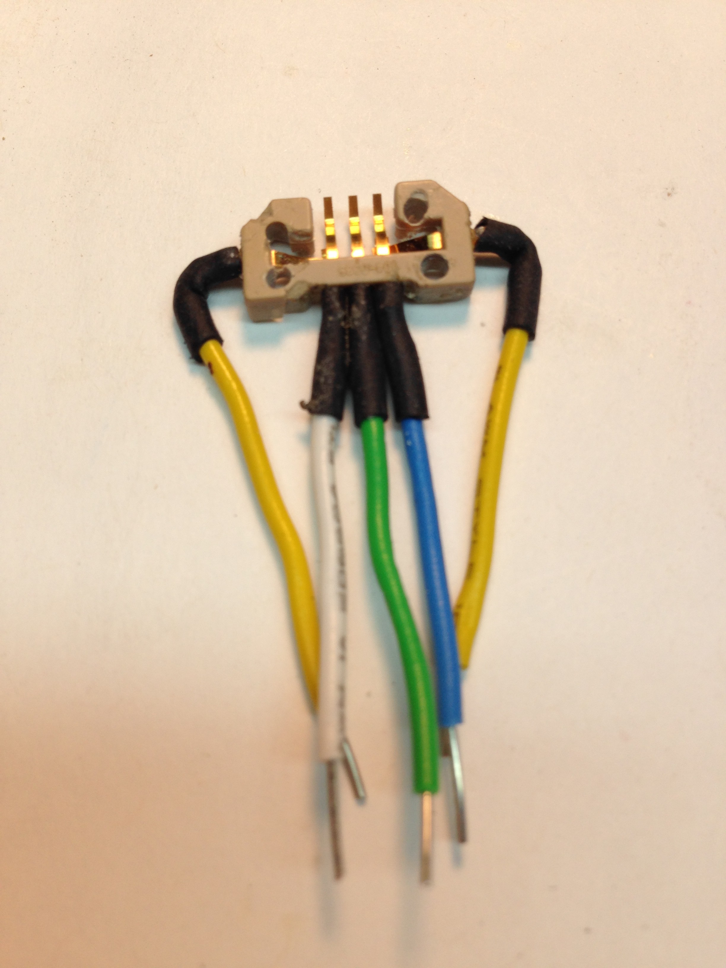
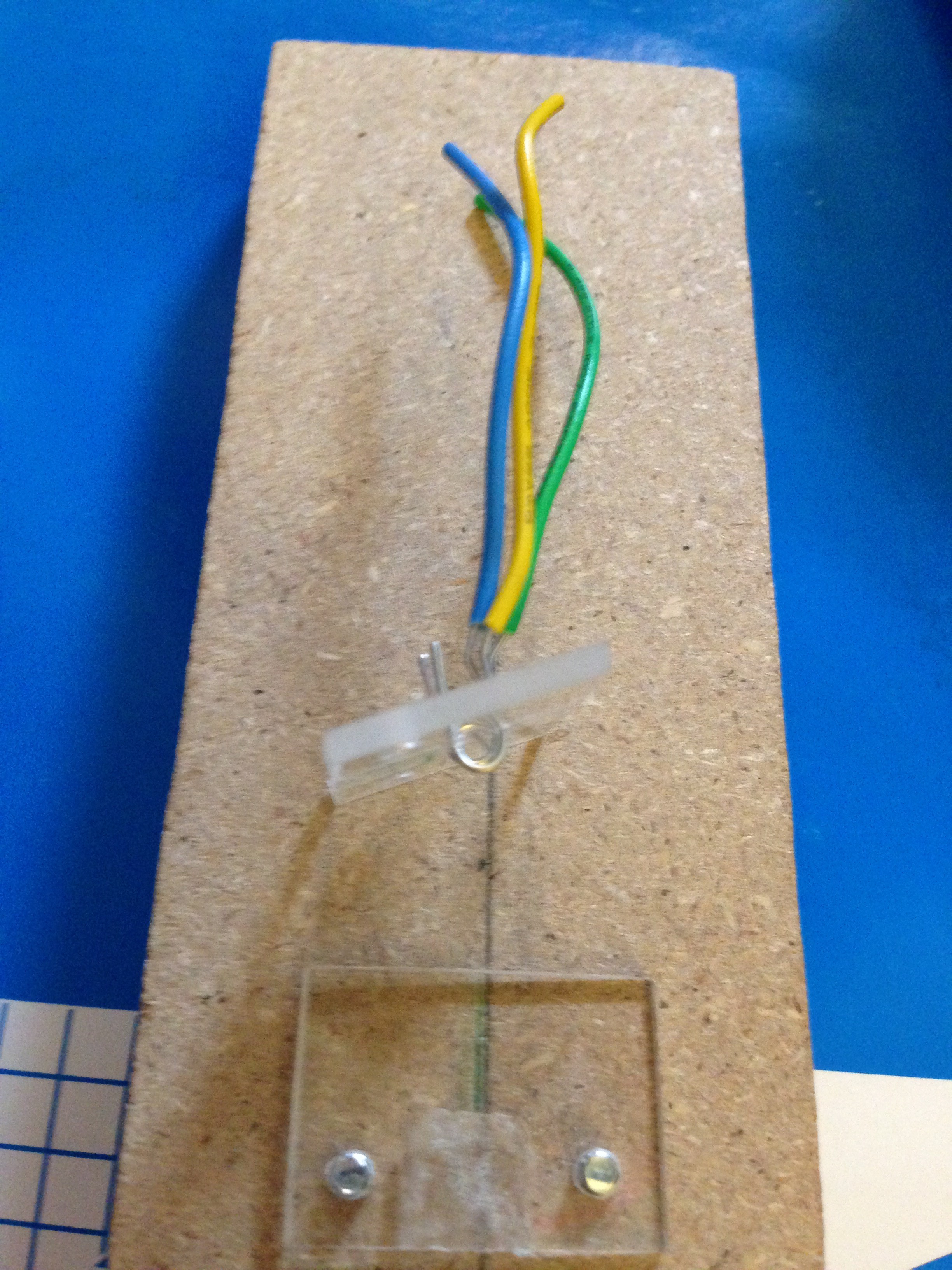
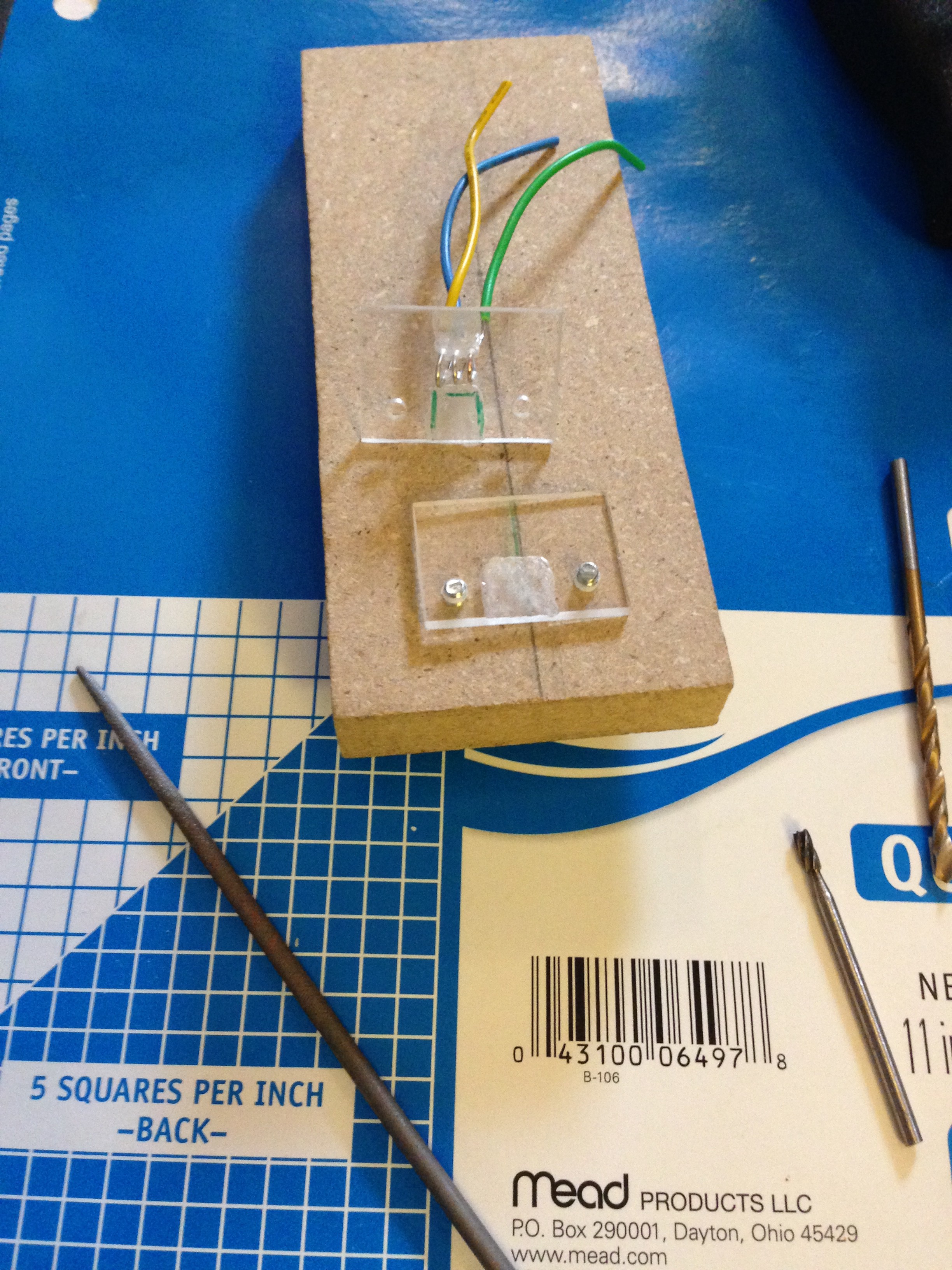
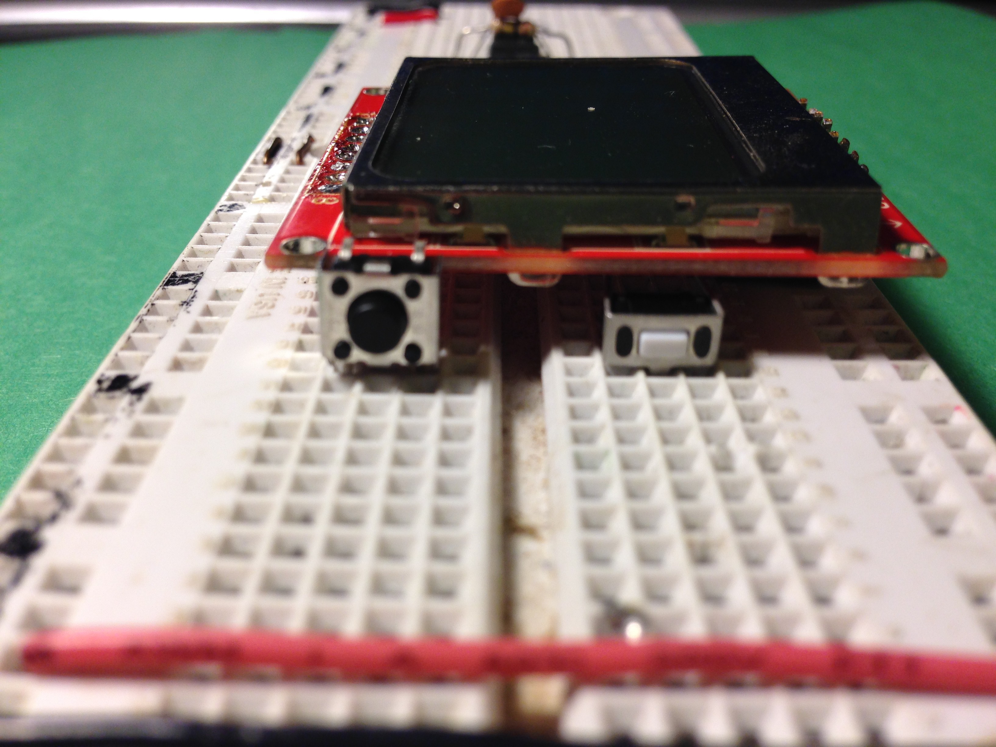
So far I've been able to do a fairly significant amount of research into how current meters work, as well as breaking down the two meters in the project photo.
Luckily, it turns out that the functional design for a Glucose Meter is fairly straightforward (and widely published)....
Read more »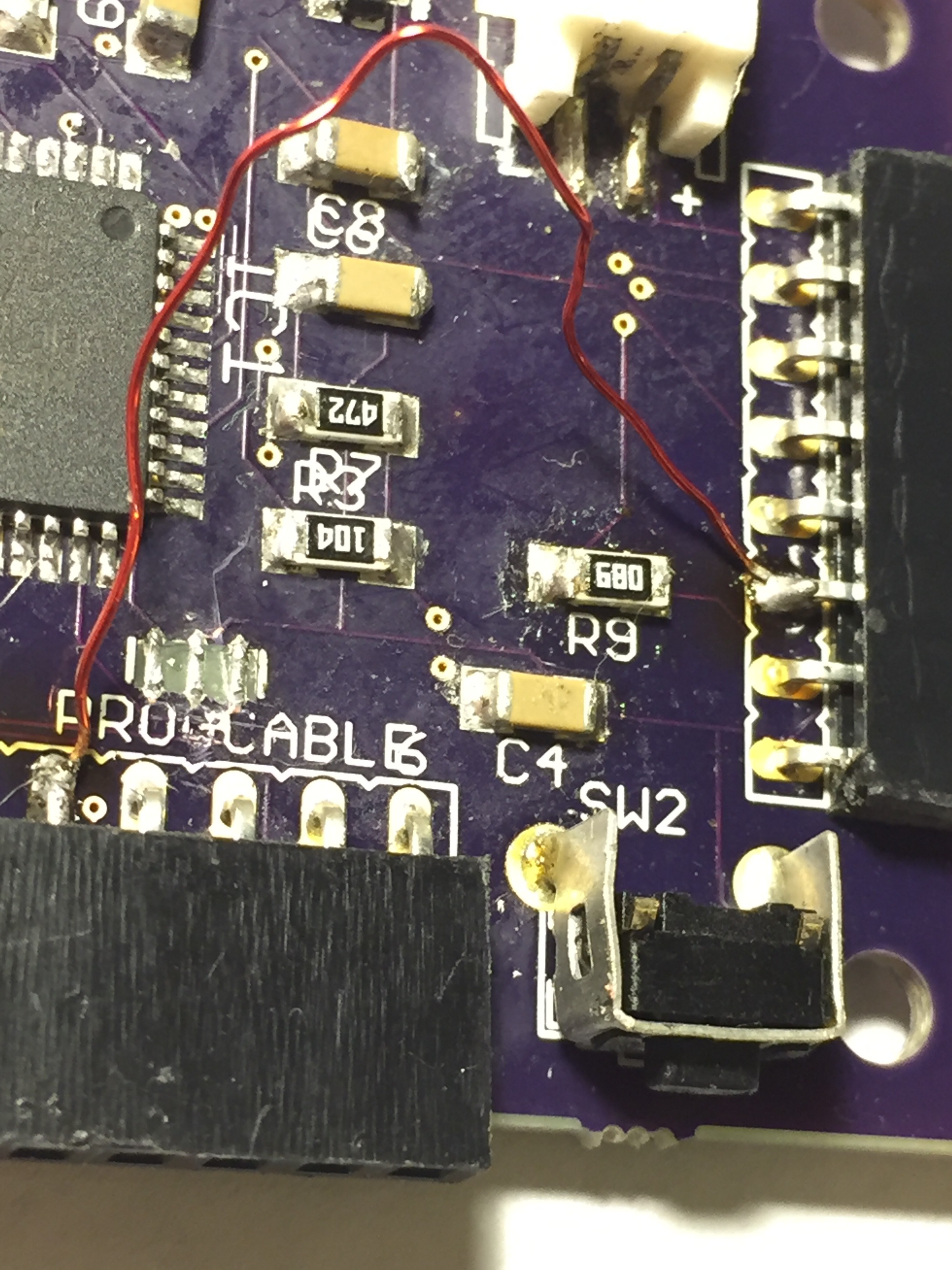


 Illinois Space Society AV
 lawnmowerlatte
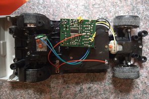
 Blake W. Ford
 uri.shani
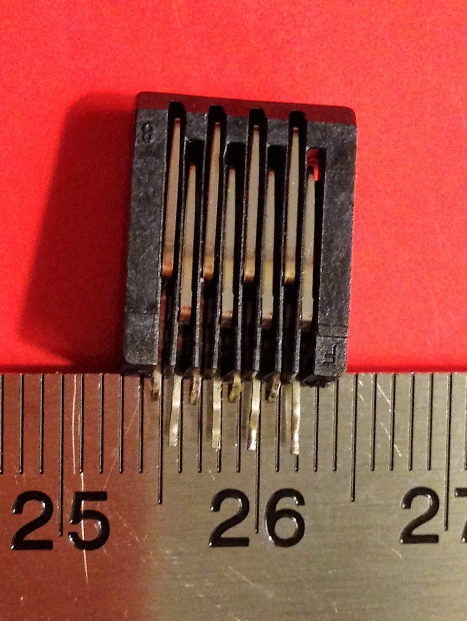
Hi, sorry that this is a super late question. This might sound stupid, but how did you get your strip reader? I was looking at a similar project and they got their reader through their company. It is my understanding that you made your own. However, please correct me if I am wrong.