 Tom Meehan
I've been going through my design (schematic's, etc.) and coding (quite literally line by line with datasheets in front of me) all week. Finally, I believe I've found the errors that broke the code - both are a mix of hardware and software.
The first issue, which I found fairly quickly, has to do with test strip sensing - when a strip is inserted. The original code that I was building on relied on using the XXX strips which have a straight contact across the bottom of the strip so that when it is inserted it completes a circuit (basically). I had attempted to adopt that to other strips that do not have that straight contact bar across the bottom.

On the PIC16F1789 the external timing crystal or oscillator needs to be connected across A7 and A6 (pins 31 and 37 on the surface mount package I'm using). If that wasn't enough - I attached the digital input for Switch 4 to pin 31 (A7). So, of course I need to change the input pin for Switch 4.
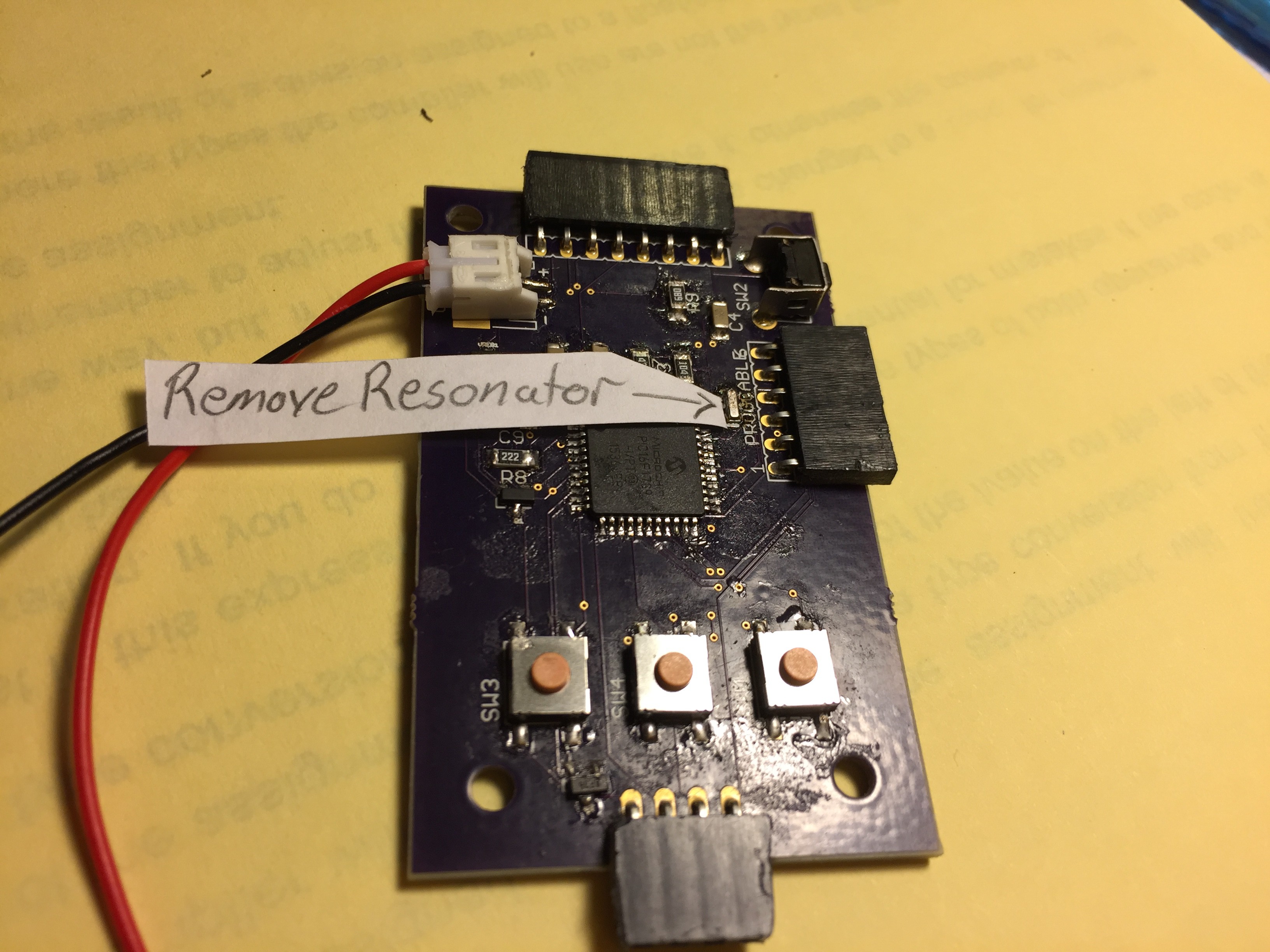
Just to get back to a working prototype, I've changed the code so that the strip sense pin (which has a pullup resistor on it) is attached to a reed switch that when triggered pulls the pin to ground potential. I also switched to the internal oscillator (4MHz) to avoid needing to solder wires directly to the chip.
After it's working correctly, again, I'll implement a simpler variation of a reed switch into the strip reader/contact housing. Also, I'll be posting all these corrections to the schematics and gerbers for the board ASAP.
In addition, I'll be adding 1 more pin to the strip reader connector, to monitor the "Fill" detection electrode.
Discussions
Become a Hackaday.io Member
Create an account to leave a comment. Already have an account? Log In.