 Yann Guidon / YGDES
It's time to think more about the sequencial logic.
For a 16×16 bits mulitplication (or division), 32 clock pulses are necessary. In general 2N pulses are required to calculate the product of N-bits operands. What is the most efficient design that creates just the needed number of pulses ?
Shift registers
A cascade of DFF is easy to conceptualize. The operation mode is simple:
- Clear all the DFF
- Apply the clock pulses to all the DFF, their data input coming from the precedent DFF's data output. Except for the very first input which is tied to logic 1.
- When the pulses are sent, the shift register will be progressively filled with 1s
- The last DFF will indicate that the counter has expired when the 1 reaches the end of the cascade.
Cost: 2×2N relays, or 64 SPDT in our case...
Johnson counter
This is a great enhancement to the previous system. The propagation of the 1s is recirculated after undergoing a logical inversion, which cuts the number of relays in half.
With 32 relays, 32 pulses can be generated before the state of the shift register is repeated. However the end of the cascade will see a change from 0 to 1 then back to 0. This last front must be detected with a "divide by two" circuit, adding 2 relays... so the total is 34 SPDT. Nicer but still not there...
Synchronous binary counter
In the spirit of Simon Winder's design, we can also use binary coding to create the counter. The number of gates/relays is reduced to O(log2(N)) but multiplying factors appear because there are 2×log2(N) DFF but also more gates to compute the next state, using an incrementer circuit. This circuit is described in the above video/link and in the below illustration coming from the ever useful Relay Trainer project page:
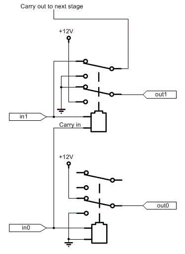
At 2 SPDT per bit, a 16-bits counter requires 4 stages × 4 SPDT => 16×SPDT.
That's better but... still not optimal.
This can be further reduced by using an asynchronous ripple counter, which is a cascade of "divide by two" circuits. It's one very simple circuit that is based on the D-flip-flop:
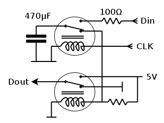
Now two things must be done:
- loop the data output back to the data input
- invert the value (exchange the 0V and 5V contacts) for the output relay.
This way, for each clock pulse, the relay will flip its state. This divides the clock frequency by two !
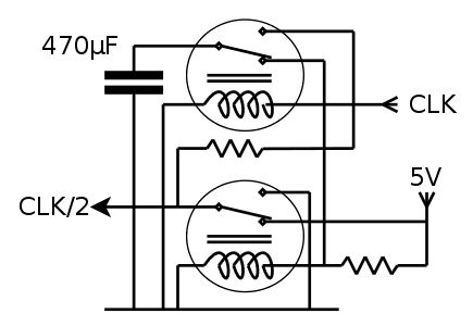
For 16 bits, the circuit must count from 0 to 15, so there are 2×4 SPDT relays in a cascade.
This is 8×SPDT. A last circuit is necessary to make this divider fully functional: a set-reset latch must control the start and stop conditions.
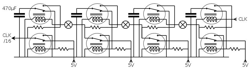
With 4 relays for the clock generation, and 10 relays for the counter, the total is 14 SPDT. The following version uses only 12:
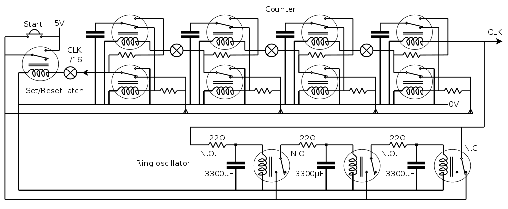
When you press the Start button, it should generate 16 short pulses on the CLK output.
Erratum : the above circuit would only generate 8 pulses... I must redesign the set/reset latch. The last DFF stage is almost transparent/useless...
Update n°2: the above circuit needs a diode to isolate the capacitor discharge from the other coils, or the time constant will be reduced...
Discussions
Become a Hackaday.io Member
Create an account to leave a comment. Already have an account? Log In.
I clearly need to add handling of capacitors and resistors to my relay logic simulator I'm currently coding so I can simulate your designs properly :-)
Are you sure? yes | no
You got my attention.......
Are you making a sort of front-end to SPICE ?
Are you sure? yes | no
No, just a crude general purpose relay logic simulator that simulates how voltages propagates thru the the structure in discrete 1 ms steps.
The "schematics" is read from a text file and the results for each step is displayed on a text-based gui. The layout of the gui is specified in another text file that belongs to the schematics file.
Currently it supports relays with settable energize/release and transitions timings, diodes. And also got built in pulse/clock generators.
Working on supporting toggle switches for gui so inputs can be given while running. Also on macro definitions of the schematics data file to reduce the amount of text that need to be typed for wider structures.
I'm writing in in golang so it will run under most systems and only require a single executable (no dll/library requirements at all).
For example the test file for a full adder looks like this, I can then in the gui file setup to display the state of the relays and the voltage levels on the wires/nodes.
CLOCK ClockA
OUT A
RATE 10
PATTERN LH
CLOCK ClockB
OUT B
RATE 20
PATTERN LH
CLOCK ClockC
OUT Ci
RATE 40
PATTERN LH
RELAY Re1
COILA Ci
COILB -
C n01
NO -
NC +
RELAY Re2
COILA A
COILB B
C SUM
NO n01
NC Ci
RELAY Re3
COILA A
COILB B
C Co
NO Ci
NC A
Are you sure? yes | no
I believe you should create a full-blown project now :-)
I was hoping it was written in JavaScript so I wouldn't have to install yet another software package... unless you create and maintain a Linux package for RH&Debian ?
Are you sure? yes | no
The good thing with golang is that no installation or packages are necessary. Just drop the exe on the desktop and click on it. Everything is self contained and fully statically linked. If some asset files are required they can easily be included inside the exe and used directly from there.
But I get what you are saying.. I'm actually thinking of having a web based gui as well connected to the simulation engine so it can be run as an online service instead.
Some years back I did quite a lot in node and javascript, but that is really not my cup of tea since I'm really a C coder. So I abandoned node two years back and went over to golang instead.
Are you sure? yes | no