 Yann Guidon / YGDES
The result of these last days of thinking is shown below, with a "simple accumulator" version.
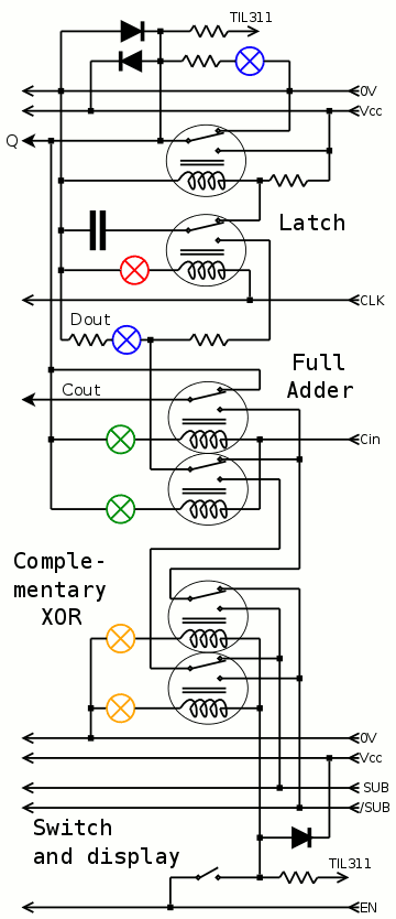
I've been careful to connect the relays in ways that avoid long chains of contacts and overload of relays. For example, there is no direct path between any input and any output. This is essential for reliable computations.
It looks obvious now that DPDT relays would reduce the number of relays. This will be for another time, if any, but that's one of the lessons I learned. Maybe I could/should put relays in series to increase the voltage and reduce some losses and simplify things a bit but... meh.
One of the "innovations" (ahem) is the "complementary XOR" stage. Since I haven't found a simple, reliable way to remove one SPDT, I'm stuck with 6 relays at this stage. So I moved things around and came to this version where the complementary value of the switch is provided, inverted by the SUB signal (and its new companion /SUB).
The advantage is that the carry is garanteed to only affect one (pair of) relay, and the CDP (critical datapath) is as short as possible. You never know.
I've added color-coded lamps:
- yellow for input
- blue for results
- green for intermediary values (in series with the coil for more blinkenlightung and some power saving)
- red for control signals
Obviously absent from the above is the Left/Right shift in the feedback path but that's just 2 more relays. It seems I won't have enough greens or reds but... damnit. I'll use yellows instead for the MUX, as one of them will be ON as a single row, no confusion is possible.
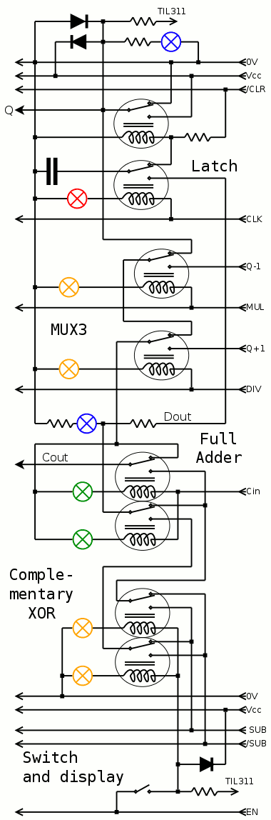
(updated to add the /CLR signal)
Another interesting aspect is the freewheel diodes : only one is needed in the switch part because the current goes only in one direction. The "bussed" control signals (EN, SUB, /SUB, DIV, MUL, CLK, /CLR) can have a single diode, in parallel with a small capacitor for filtering. This leaves the coils of the full adder to protect with a full-bridge diode circuit (this is not shown on the above diagram). So overall, the cost in diodes is reasonable and the operation can be almost quiet (EMI-wise).
Next on the list : characterise the couple lamp/relayin series to find the best power supply voltage, and find which series resistance is best for the latch.
I could also put all the coils of a nibble in series and have 10V control signals for DIV, MUL and CLK, which would save some lamps... The lamps are given for 3V and the relays can do 2.8V so (2.8×4)+3=14.2V max. A 12V PSU could work because latch is at 2V (=>10V). A cap in parallel with the lamp would provide another kick.
Discussions
Become a Hackaday.io Member
Create an account to leave a comment. Already have an account? Log In.