 uri.shani
I published a short survey this week on facebook and twitter, aimed at helping me understand more what are the main reasons people don't just go and build their own MIDI controller. If you follow this project, it will be great if you could share this, so I'll get some more replies.
Now more to the point - while I was testing my first designs, I wasn't thinking of a full test procedure, but rather of getting everything to respond. Moving forward to writing comprehensive blocks, I was building the full functionality into the Arduino model sketch, and I came to realize how flawed my design was. So - it's redesign time!
First, I redesigned the DI/DO matrix shield. I updated it to use a single MCP23x17 , and based on Microchip's app note, I've also eliminated most of the small components. Should have done that before I went ahead with the first design, as it wasn't based on an I/O expander, but on shift registers. The app note states that pullup resistors on the inputs help define the time between allowed button presses, but I decided not to include those in this revision. If the current revision will prove to be too "jumpy", I've left enough space on the board to allow for the addition in the next iteration.

The PCB is not yet fully decided upon, but here's a snapshot:
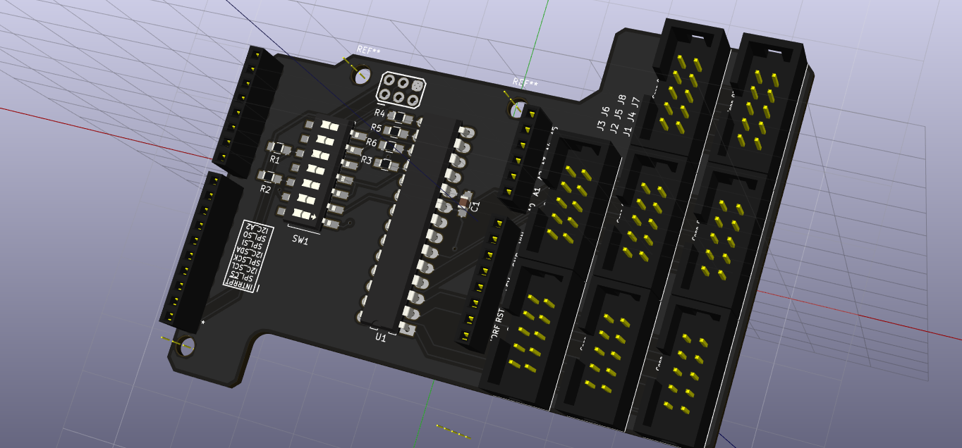
I still need to think whether to keep using DIP packages, so the user can use either I2C or SPI, or go the more economical route and use SOIC packaged chip, along with preconfigured solder jumpers. Since I aim in some way to make these boards somewhat of an introduction, I think that perhaps the DIP chips may show the intended (novice) user it's possible to make changes. As I learned from my first iteration, all cable connectors were moved to one side of the board, and were changed to 10-point IDC in order to standardize the system. The connectors on the analog MUX shield will be all moved to the opposite side, which will free some space for using both shields at once.
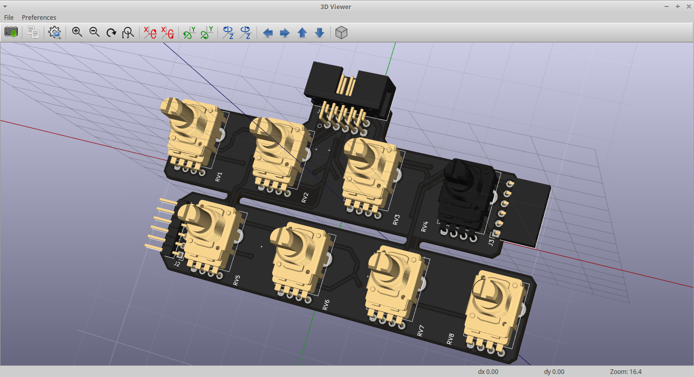
Next, I started designing the peripherals. I started out with an 8 rotary pots plug-in for my analog MUX shield. The pots are on 25 mm between centers, and the two lines can be broken at the tabs and the pots rearranged on a single line. I'm still not happy with the placement of the IDC connector, and will probably need some cardboard cutouts to play with until I'm satisfied.
I've also showed the blockly environment to some friends, and got their opinion on looks and feel. I've changed some things in the overall design, for usability. First, I changed the color scheme to imitate what most musicians are used to. I've also made programming the Arduino with the code a bit more accessible (in my mind, at least), by giving the user only the possibility to download the code and open a new window with the Arduino online IDE. I believe that serves both the purpose of shortening my development time, but also to show future users that the Arduino community is quite large, and it is quite easy to explore further if they wish.

Discussions
Become a Hackaday.io Member
Create an account to leave a comment. Already have an account? Log In.