The first two PCB's have arrived ! This is the pcb for the registers:
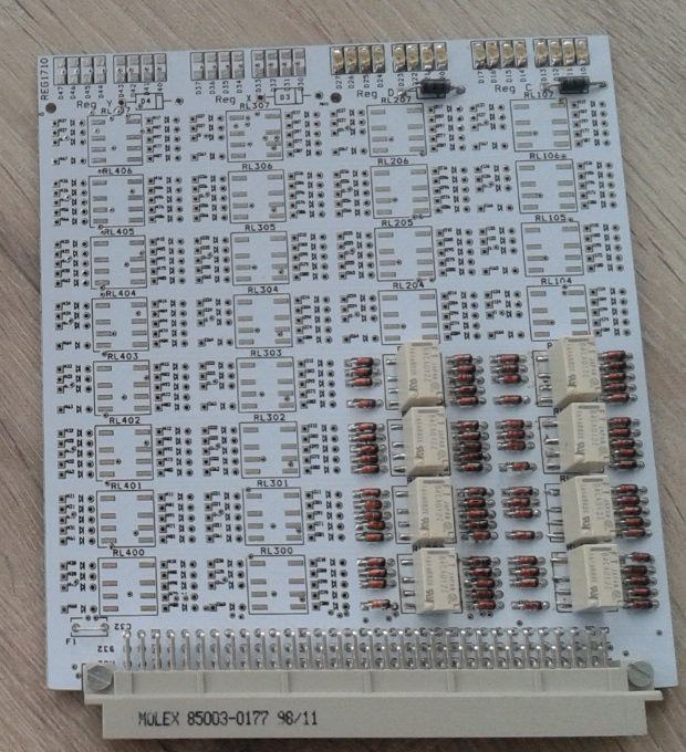
The pcb implements four 8-bit registers (registers C, D, X, Y). Only 8 bits (4 bits in 2 registers) are mounted. At the topside of the PCB, you see that each register has its own 8 LED's to indicate the contents. The pcb is labeled "REG1710" (top left) meaning the design is from 2017 week 10.
The other PCB is the 8-bit ALU "ALU1710":
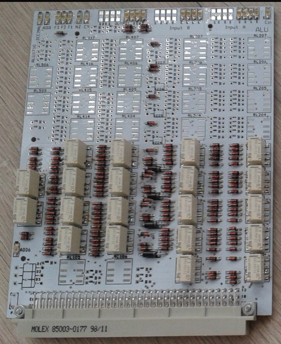
Only 4 bits of the 8-bit ALU are mounted. The 4x4 relay section is the basic ALU, that includes two input registers (latches, to be honest). The sections with 2 relays are for the ADD-6 section and decimal correction. On the top of the pcb you see LEDs for input data, output data, function selection and flags. The ALU has the normal Load, AND, OR, XOR, binary ADD, but can also ADD decimally and convert BCD data to 7-segment display code. Subtraction needs help from outside of the ALU. It is done by inverting one of the register outputs (and setting the CY-input).
The placement system is all diodes and relays on top, and the resistors on the bottom. Relays are surface mount types, this gives more space for routing at the bottom. Diodes are through-hole 1N4148. I did not use BAV99 or other SOT23 types (otherwise I could be accused of using transistors secretly ;). Mini-Melf were also avoided since they tend to roll away when you try to solder them. Some signal wires drive many circuits, in that case the diode is 1N4004 or similar.
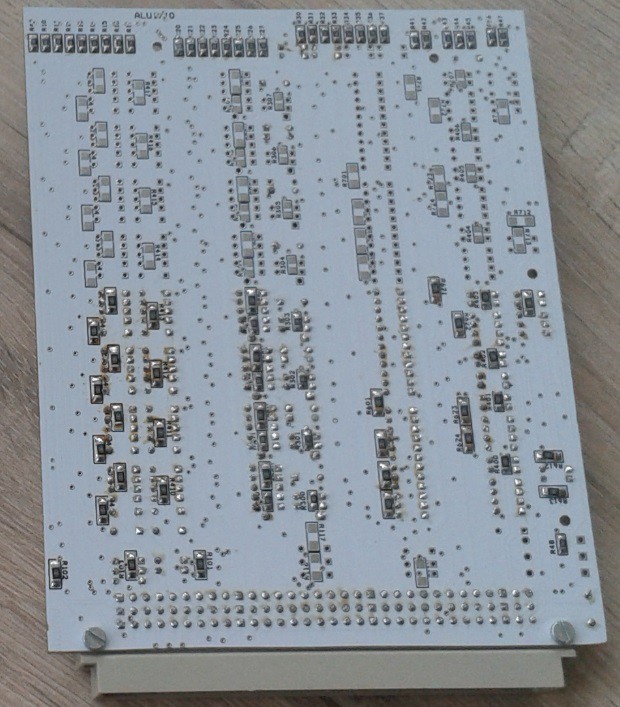
Of course, something was wrong. The connector DIN41612 was not close enough to the edge of the pcb (placement was based on the silkscreen of the footprint, I interpreted one of the silkscreen lines as the edge of the pcb, but that was wrong). I had to remove about 1mm of the pcb to make it fit. This destroyed only a few traces, that must be replaced by a wire.
Schematics and gerbers of REG1710 and ALU1710 are in the Hackaday files section.
I did built a simple test device. The ALU and REG pcb's can be connected to it. The 3x4 buttons transfer data from a register to the input A of the ALU and from the ALU to a register. The 8 buttons on top control data on input B (next to it are a CLR input B button and a CY-input button). The big knob selects one of the ALU functions, the function is displayed by one of the green LEDs.
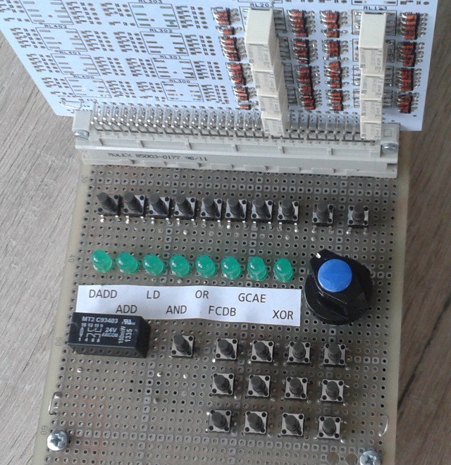
For the curious readers, here is the bottom side of the test device:

And of couse, I tested my new pcb's. Found a small problem:
It was intended that all diodes point in the same direction. But a few diodes on the ALU picked an older diode footprint, that had the silkscreen in the other direction. The result was a few diodes had to be reversed.
After that was done, all assembled functions were working ! (But the tester does not test the second output ports of the registers).
-------------------------------------------------------------------------------------------------------------------------------
Some new instructions were added to the instruction set:
- An instruction to load data from the program memory. The simulator has a unified memory, so the instruction was not needed there.
- Added XOR with immediate value
- Added a powerful instruction: Test a bit and branch. Within a single instruction, a single bit from a register pair can be tested, and a branch forward is done if the bit is 1 (or 0). In each register pair, the bits that can be tested are 0, 1, 2, 3, 4, 7, 15, 31. So this also replaces the clumsy sequence that was needed to test the upper bit of a value in a register. Instead of adding to the PC, this instruction can also conditionally add to register C. The branch forward has a reach of 31. In the instruction space, some space in the register-mode was sacrificed to make the test-and-branch possible.
Work will continue with the details of the control functions, and planning the "backplane".
Discussions
Become a Hackaday.io Member
Create an account to leave a comment. Already have an account? Log In.
Cool! Congratulations with active assembling!
Are you sure? yes | no
Very nice !
Are you sure? yes | no