 Ted Yapo
I'm a sucker for surplus electronic crap. When I recently saw a one-day sale at Electronic Goldmine with 150 relays for $10, I couldn't resist. Being SPST normally closed, they're not the best for building logic, but I figured I could make them work. FDH400 diodes were also on sale 500/$3, so I grabbed 1k of those just in case.
I figure since the relays are somewhat contact-deficient, it's fair to use diodes, too. Besides, the relays have built-in catch diodes, so short of performing surgery on each one, I'm going to end up with diodes in there anyway.
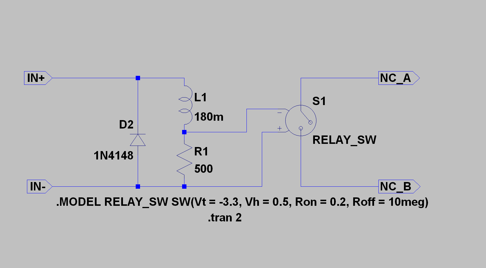
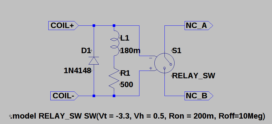
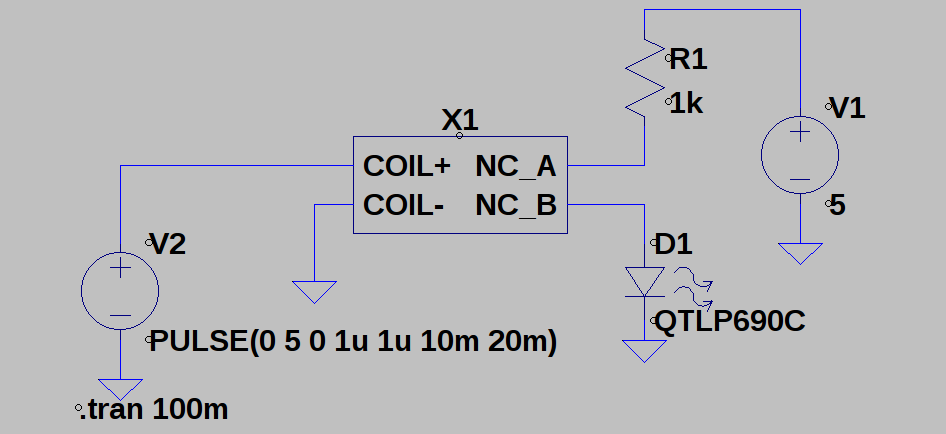
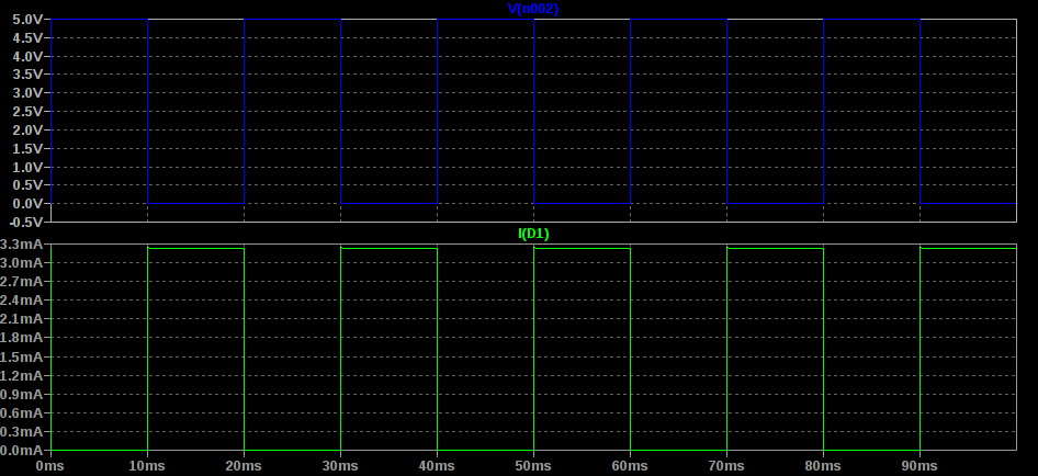
The basic building block I'm going to use is an inverter made with one relay:
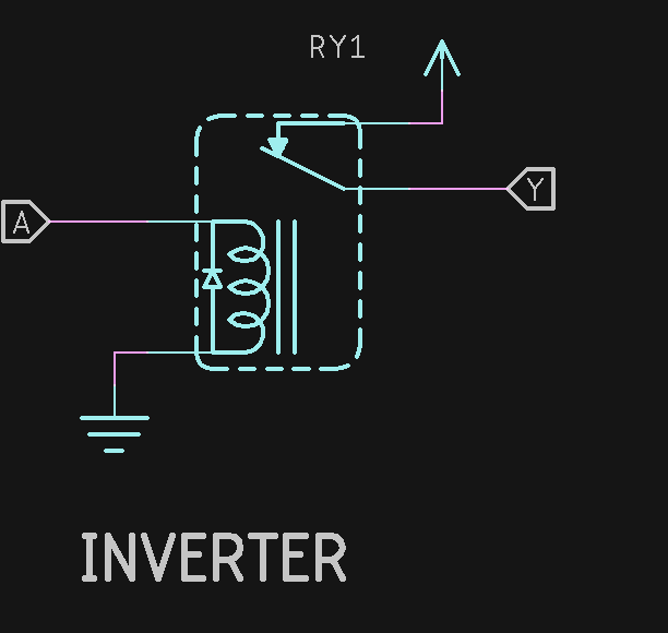
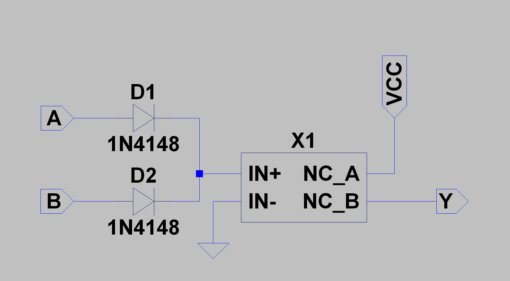
When A is high (the relays have 5V 500-Ohm coils), Y is low, and vice-versa. It's trivial to add a diode-OR gate to this to make a NOR gate:
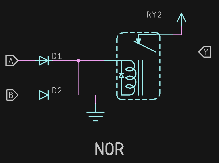
This is equivalent to the usual NOR gate:
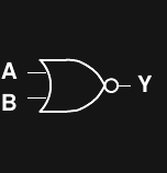
When either of the A or B inputs is high, the output is low. Given the NOR, an RS latch is easy to build:
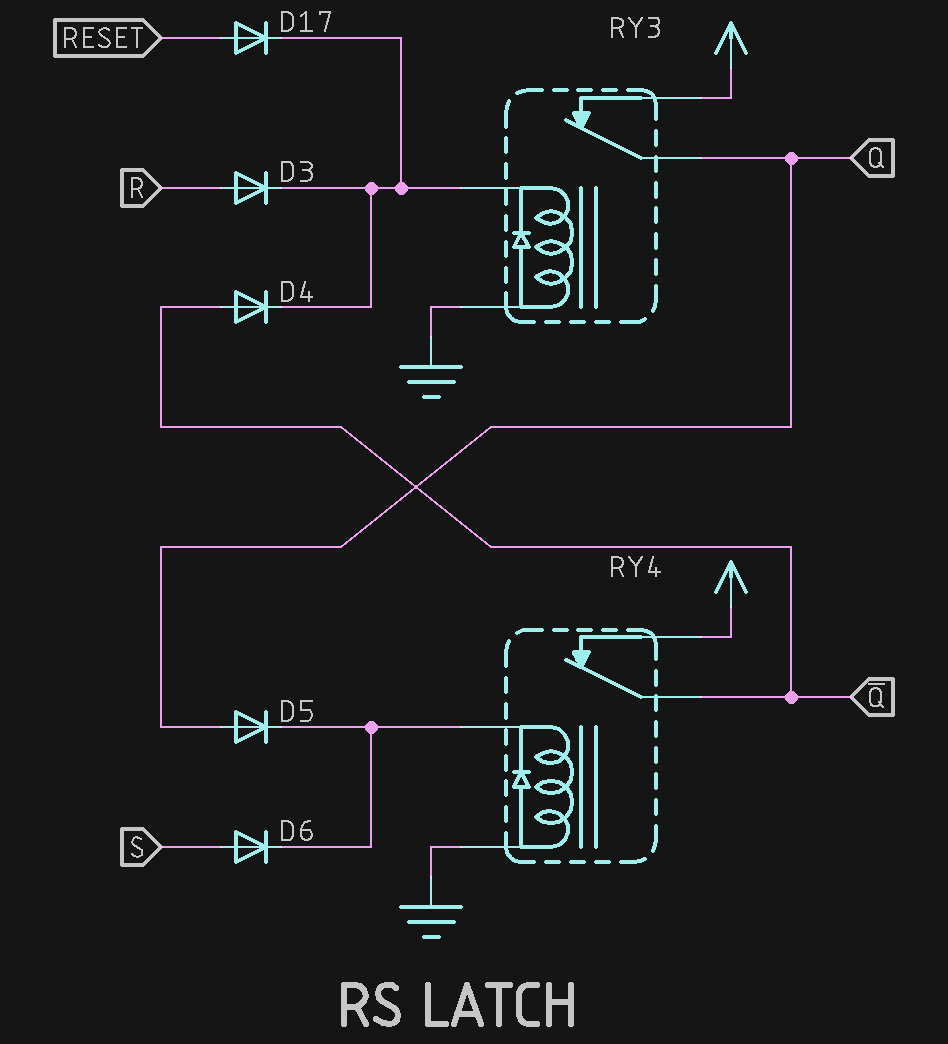
This is similar to the usual latch circuit:
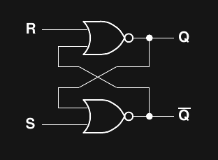
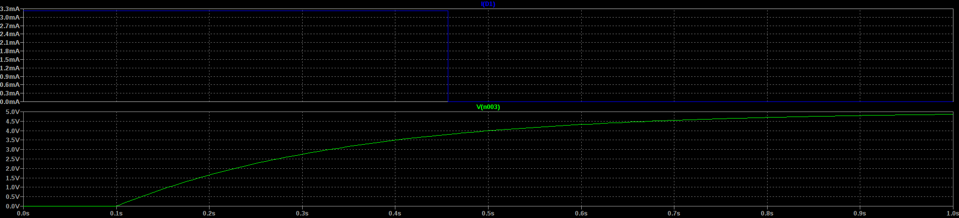
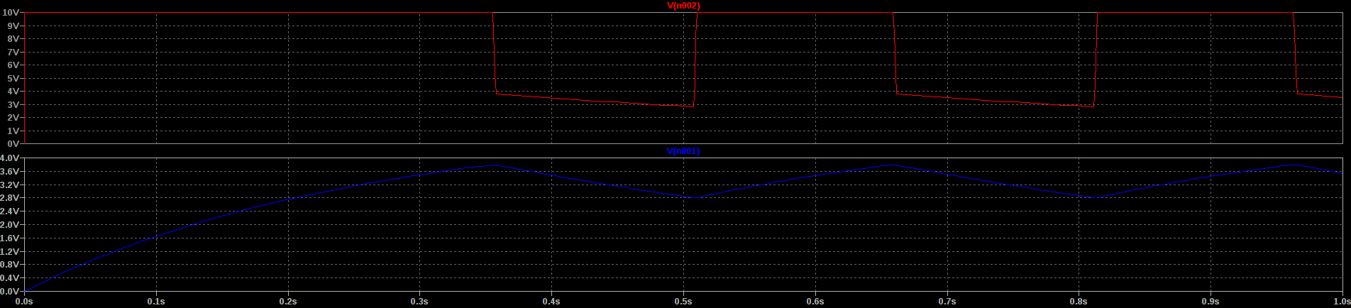
But, there's one important difference. With the NC relay version, at power-up, the relays won't settle into a stable state. Instead, they'll just buzz, since the contacts will try to energize both coils at once. This is a case of metastability, but with relays it doesn't just mess up your timing, it fries your components. To avoid these problems, each latch in the system will need a reset diode (D17 above) that will ensure it assumes the correct (stable) state at power-up. The common RESET line will be driven from a relay delayed with an RC circuit.
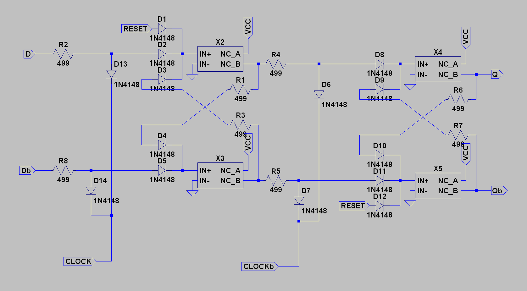
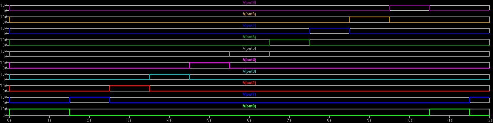
The next step is to make a clockable flip-flop. I've chosen the classic two-stage topology:
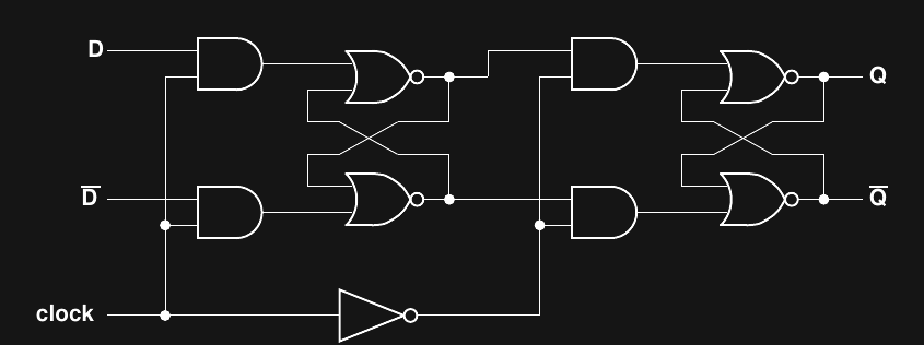
I chose this topology because it can be done with only four relays. The diagram below shows seven relays, but three of them (at the bottom) are for the clock signal, and those get amortized over all the circuits in the same clock domain. And, if you have an inverted version of the clock signal available (say from a previous counter stage), you only need two of those. It's a normal two-stage flip-flop arrangement, with the inputs to each stage gated by opposite phases of the clock signal:
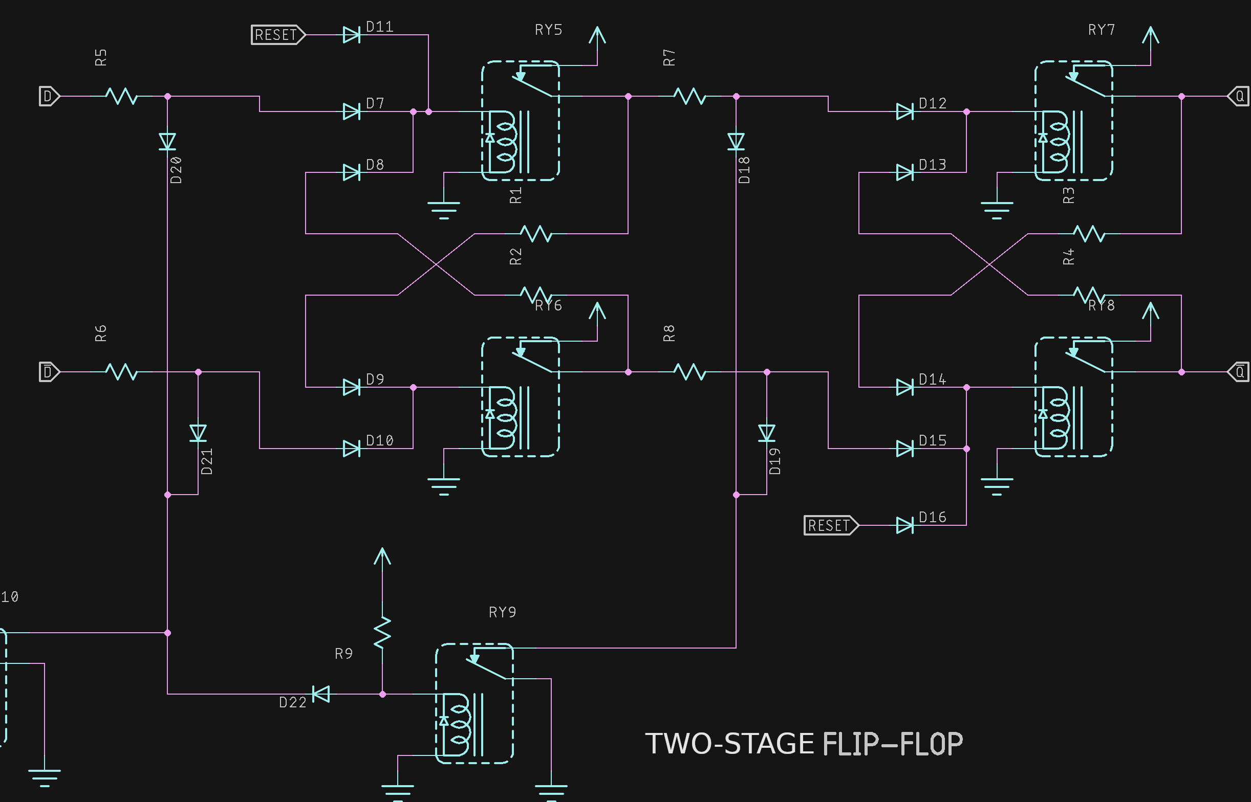
In the diagram, I've oriented the OR-diodes horizontally, and the AND-diodes vertically. Since the AND gates need to pull down the high level inputs, resistors are used in the signal lines. These resistors will have the same nominal resistance as the relay coils (499 Ohms) and the circuit will use a 10V supply instead of 5. You usually see an inverter used to create Dbar from D at the input to make this a D flip-flop. But, if you are just going to use them in Johnson (twisted-ring) counters, like I am, there's no need for this extra gate. The Q and Qbar signals can feed the next stage's D and Dbar directly:
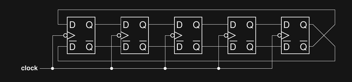
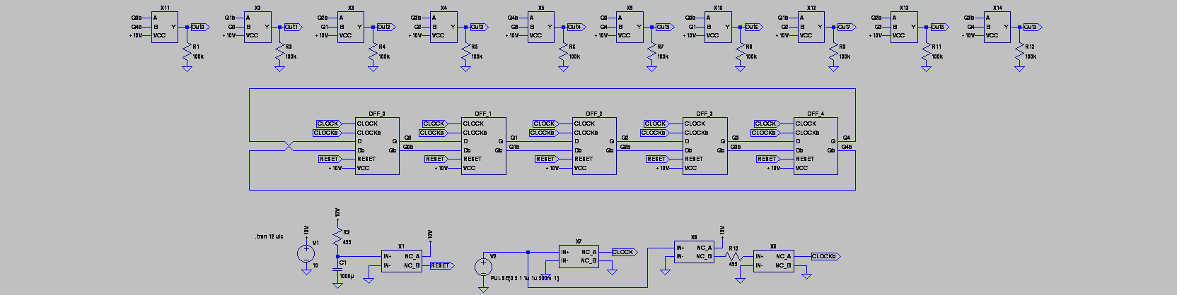
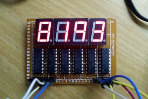
It's a modulo-10 counter perfect for the ones digit on hours, minutes, or seconds. It needs 10 more NOR gates for decoding, but those could drive Nixies directly, or 7-segment displays through a diode ROM.
This isn't the fanciest relay logic you can make (unlike some of @Yann Guidon / YGDES highly optimized designs), but it should work first-try, and is easy to wrap my head around.


 Tim
Tim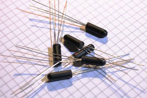
 Yann Guidon / YGDES
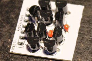
 HummusPrince
That is an odd configuration for an SPST relay, have never seen one with NC contacts only. That might be why 150 of them sold for $10 though.