 Casual Cyborg
For the previous blog entry, read Assembling the Board Part 1: Fried Board Recipes.
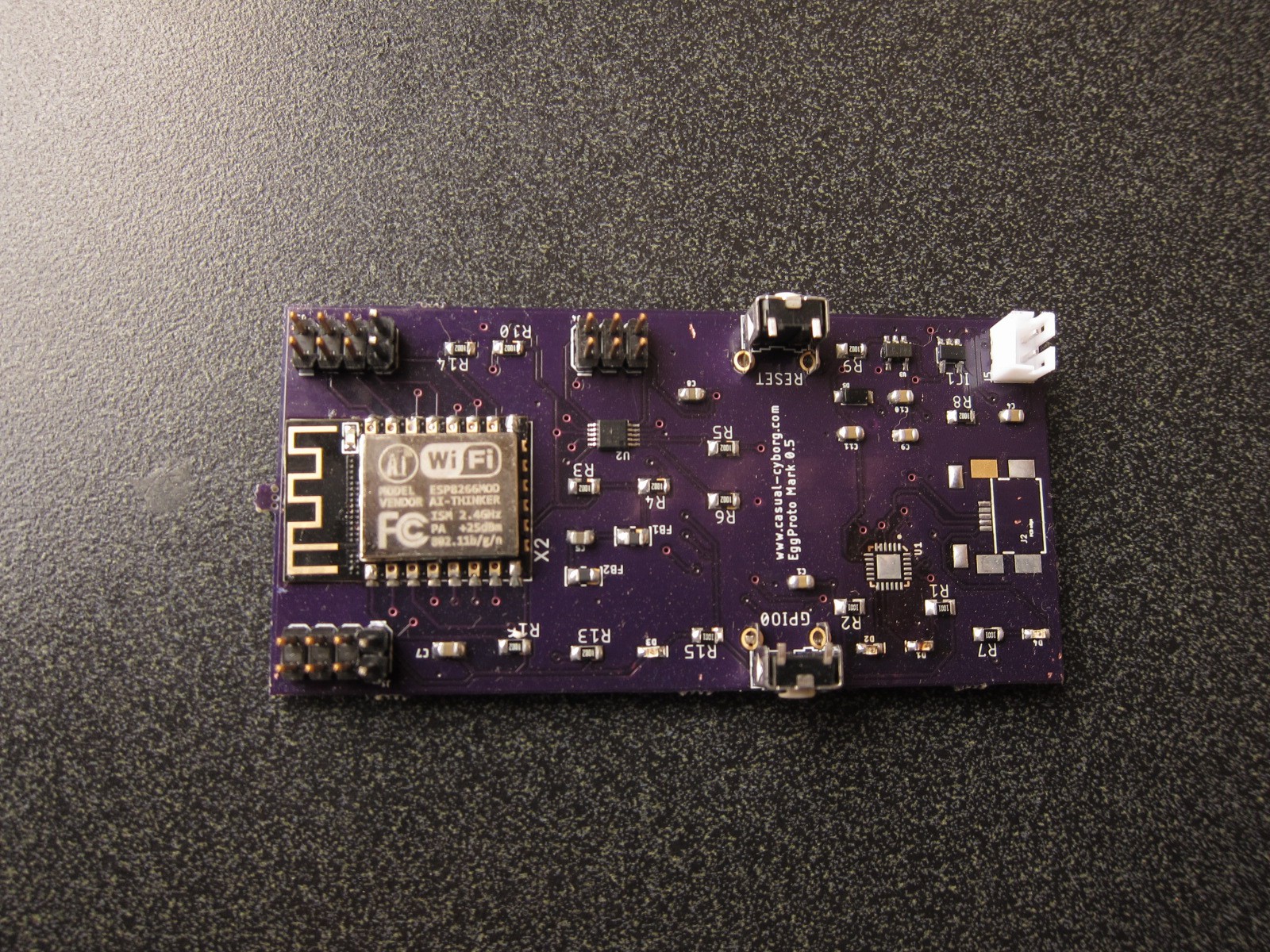
So I managed to finish assembling the rest of the subsystems of the board.
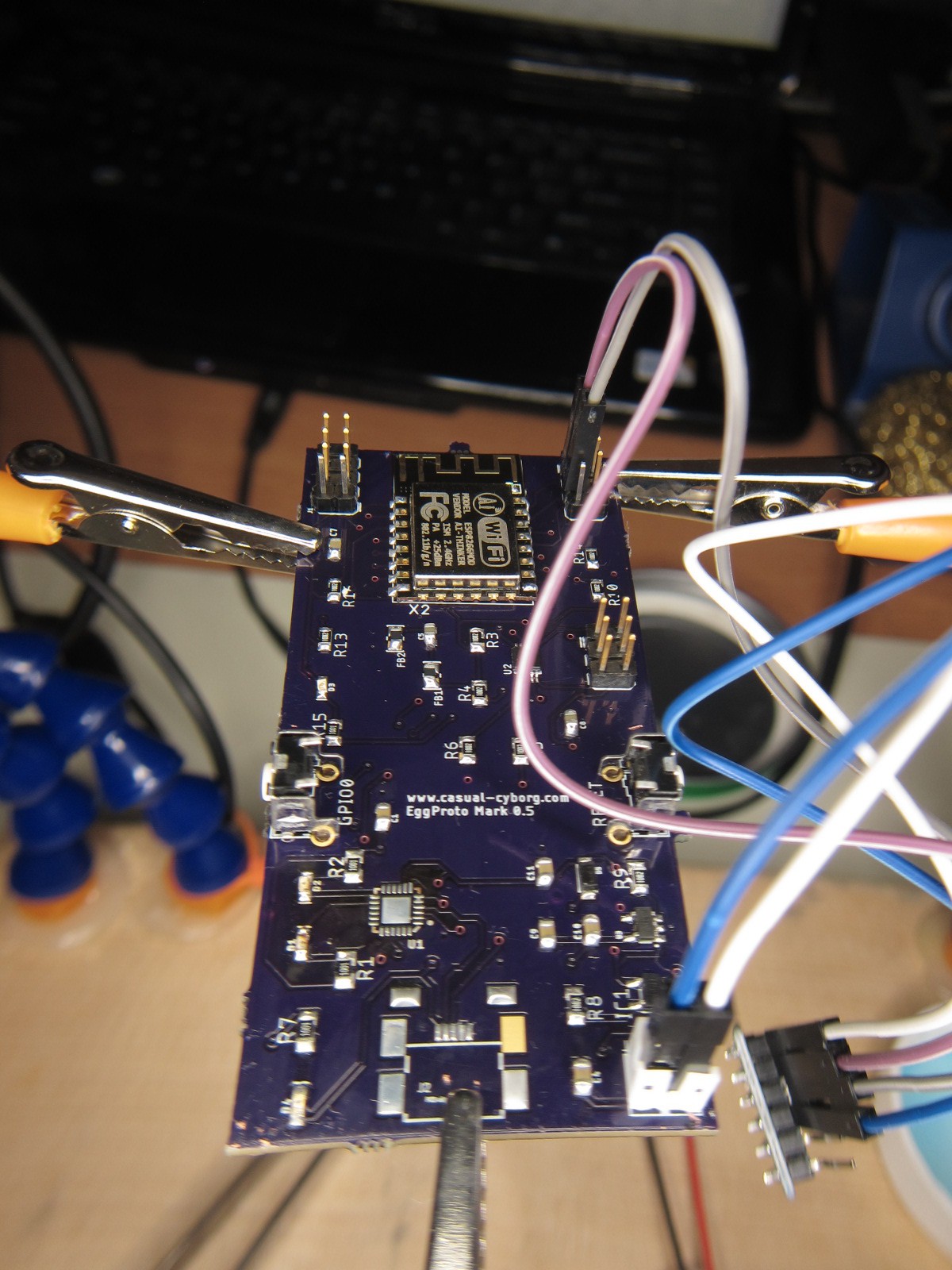
After, I think 3 more attempts to solder on the QFN package, and finding that the voltages of the CP2104 weren't, well, doing what they're supposed to be doing, eg. I have a VBUS of 4.75 V, and there "should" be a VOUT of 3.45V, only to see 1.6 Volts coming out, I decided, OK, you know what? Let's just get the other subsystems that I know should be working, working. which means the ESP8266 and its supporting electronics, the redundant power supply and battery charging system, and the ADC system. None of those have strange soldering issues. I'm not sure if while doing the hot air method if I basically shorted the CP2104 and did something odd to it, or what.
So, to see if I could get some answers, I headed over yesterday to HacDC, where I met one Julia Longtin, who placed in the 2014 hackaday quarterfinals with her Microwave Aluminum Printing Technology.
Julia pointed out that I was hitting a problem with temperature differentials in the QFN package, the solder, and the board itself. The board needed to be at a higher temperature for the solder and the chip to adhere solidly. Which meant heating the board, either with a soldering hot plate, an electric skillet, or with a freaking flood light?!!
Given how new I am to hand done SMD/SMT soldering, Julia gave me a crash course in using a flood light that we salvaged from HacDC's extensive, um, "storage" facility, aka place where a lot of stuff ends up. Anyone need an analog oscilloscope? They've got tons to give! Shoot, I have two to give...
So, the next thing I need to do is to get a hot plate, and some ramen. Because SMD soldering gets me pretty hungry. Till then, I have to make do with the board like this:
The other problem I ran into is I specced out the incorrect USB micro B connector! It's times like these where I wish I was in Shenzhen. Instead of hunting through an online catalog at Mouser.com, reading confusing datasheets where the mechanical designs aren't always up front, I'd much rather be able to go out the door, go to a shop, and check out what they've got, touch em, feel em, take a look and get a good idea of what I want. This whole catalog and pray method isn't the best way to prototype.
Up next, more adventures in SMD/SMT soldering, and creating some of the first use cases! Stay tuned!
Discussions
Become a Hackaday.io Member
Create an account to leave a comment. Already have an account? Log In.