Close
0%
0%

Waffle: a pocket-sized digital radio system

µController, CC1101 module and LCD forming a small communication device. Other probable uses in the near future.

Similar projects worth following
This is a digital radio system using a microcontroller, a CC1101 Sub-GHz module and an LCD. The idea is to have a pocket-sized device that can be used independently to receive broadcasted messages, or as a "modem" for the 400MHz ham band.

Right now, this device is built with two uses in mind:

  • Amateur Radio paging system. Something in the lines of a one-way system (for now): a base station made of a CC1101 plus a hefty power amp broadcasts messages over 70cm band to small modules people carry around. The small receivers include an LCD and buttons to display and acknowledge the messages.
  • Digimodes interface: the CC1101 can transmit using 2FSK, 4FSK, GFSK, MSK, OOK and flexible ASK (as per the datasheet).I thought it would be interesting to make a small interface linking this module to a PC, and maybe add a small PA to bump up the power up to 7W. I never got into digimodes over UHF, this may be a chance to do so.I think non-amateurs may also use it as long as they don't use a PA and stay in the 433MHz band.

The uses can also be expanded for a more general public, for instance:

  • For weather alerts
  • For earthquake alerts
  • ...?

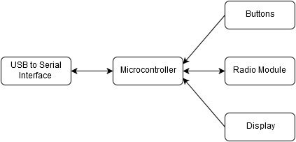
The following block diagram summarizes the inner configuration of the device:
Logs :
  1. First ideas
  2. Main board design
  3. PCBs
  4. Finding a correct name, other uses, parts coming in
  5. Waffle Modem Computer Interface
  6. Building the dirtiest UHF antenna
  7. First prototype
  8. Small progress for the Interface
  9. Wow, we were selected in the "Anything Goes" challenge!
  10. Proof of Concept

Why Waffle you may ask? Well, I like waffles, it's a catchy word, and I've always wanted to name one of my projects after food. My friend @Frédéric Druppel found a matching abbreviation for it: Wireless And Free Format Lite Emitter. Feel free to find another that matches the project's name :)

CAD models.zip

STL files for the case, bottom lid and D-pad. Solidworks source included

Zip Archive - 833.78 kB - 08/08/2016 at 21:22

Download

POC Code.zip

Arduino scripts and librairies for the ATMega328 controller

Zip Archive - 328.71 kB - 08/08/2016 at 21:07

Download

Waffle_interface_Beta_v0_2.pde

Second Beta Processing GUI file

pde - 6.33 kB - 05/10/2016 at 19:57

Download

SchemBrdDesigns.zip

KiCAD schematics, PCB design, footprints, Gerbers for the rev 1.0 board. Gerbers sent to dirtyPCBs are in gerbers/dirtypcbs.zip

Zip Archive - 971.20 kB - 04/23/2016 at 08:12

Download

BOM.ods

Bill of Materials for the rev 1.0 board

spreadsheet - 4.69 kB - 08/08/2016 at 21:19

Download

  • 1 × 3D Printed case STL Files are included
  • 1 × Assembled PCB See BOM for complete parts list
  • 1 × CC1101 Sub-GHz transciever module (10 pin version) Evaluation, Demonstration Kits, Boards and Modules / Evaluation Kits, Boards and Modules
  • 1 × OLED Display I2C 128x62 monochrome version

  • Waffle v2.0

    M.daSilva02/27/2017 at 15:12 0 comments

    As the date of my last project log shows, I haven't been working on the Waffle project lately, for a few reasons:

    • I reached the maximum memory available on the ATMega328. I'm not an efficient coder, but I realize that if I need to implement the features I want to (nice menus, file transfer interface, message saving, etc...), I'll need more memory.
    • Got involved in a 2nd masters degree until late may, I've got less time to work on it...
    • Less motivation altogether, other projects pop up in my head...

    I'd still like to move this project forward, by restarting from scratch. I've learned the following lessons:

    • SMD is not that hard to solder! As long as I stick to the pitch I've used so far, I can hand-solder it...
    • Think about battery management from the start!
    • Think a bit more about tolerances when designing 3D-printed cases.
    • DirtyPCBs is amazing.
    • PCBs with round corners are nice.

    Cue the Waffle v2.0! Preliminary specs would be:

    • ESP32 controller, would add Bluetooth/Wifi capabilities, along with the power of a 32-bit microcontroller! Still waiting on the software stack :)
    • RFM69 radio module: they seem to use an efficient digital mode, optimized for battery usage, while staying on the 70cm band.

    It'll have to wait until I make it home, get some dev boards to start designing a portable device...

  • Proof of Concept

    M.daSilva08/04/2016 at 19:27 1 comment

    Okay! I'm back, I'm alive and kicking!

    I worked on two main things: the case, and the software

    Casing

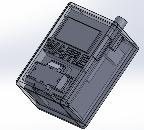
    Solidworks was used for the entire process.

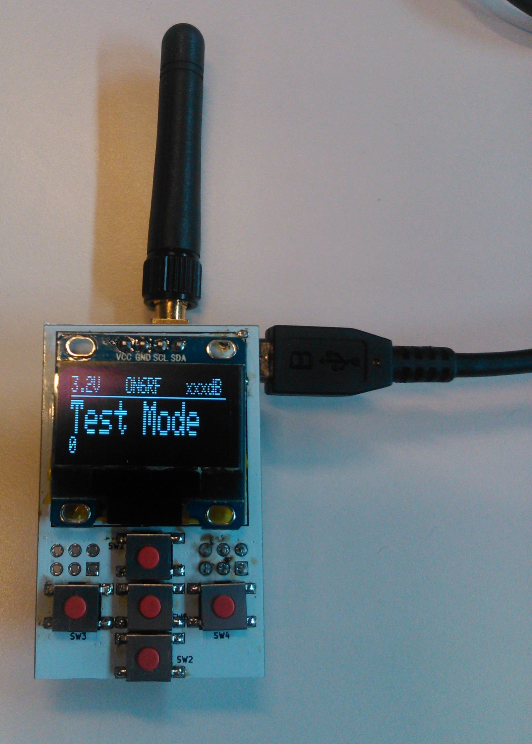
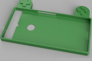
    I first modeled the actual board, before designing the case around it. The D-Pad rests against the 5 buttons. I still have to figure something out for the central button, as it's not "pressable" yet.

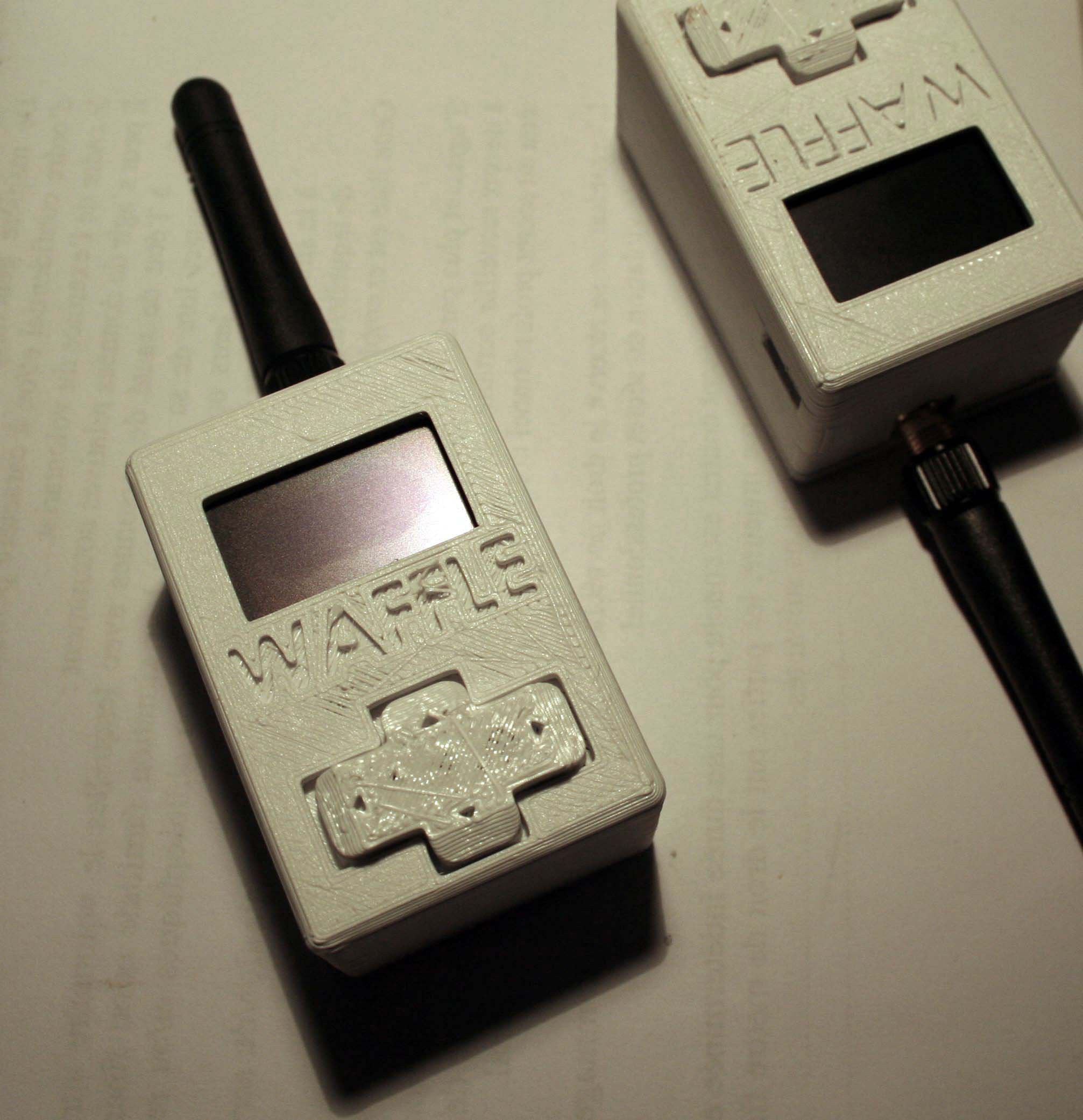
    The whole thing was 3D-printed using a Fabrikator Mini (cheap 150€ printer from HobbyKing).

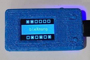
    The board fits snugly inside the case; the screen is lined up with the opening, and the D-Pad is a perfect fit: not too loose, not too tight.

    Software

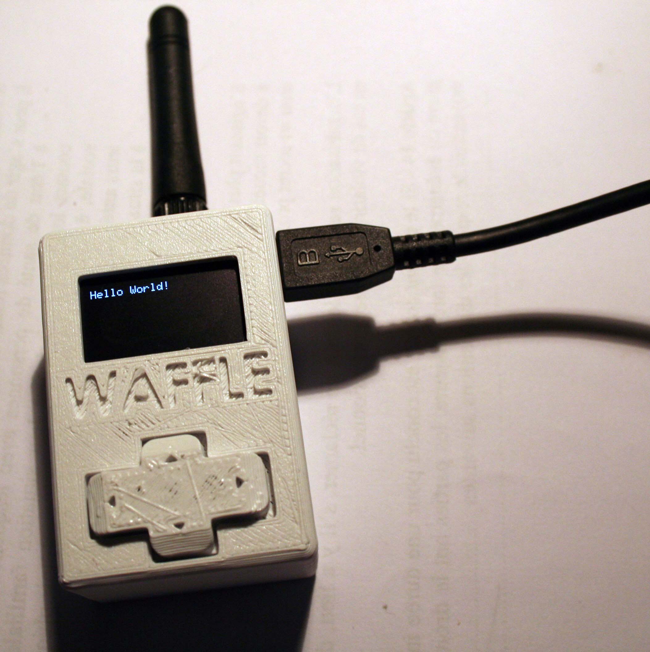
    Last time, I managed to get "bits" flying between two devices. That meant having one specific RX unit, and another TX unit. This time, I can send strings either way, spit them through the serial interface and display it on the LCD!

    All right, this is not real proof. I could've written a simple sketch that displays this at startup, without any radio interface. You'll have to trust me on this one. (Promised, I'll make a video showing the thing in action!... Sometime soon).

    As for the user interface, I may run into some problems.

    The OLED displays everything smoothly, no worries. But I will probably run out of memory before being able to implement the whole interface! I'm using the Arduino environment, with the Adadruit library. The OLED eats 1KB of RAM (the framebuffer is the most resource-hungry)! I only have one KB left to handle the CC1101 comms, serial handling, buttons scanning, battery management, ... I'm already having crashes from time to time.

    So what are the solutions?

    • Optimize the code the best I can: that's a good idea, as most of my code is badly written. Global variables, strings that are used as variables while they can be defined at compile-time, ... However, no matter how much I optimize the code, I feel like I'll always run into those issues when I'll start to add additional features.
    • Change the microcontroller for a "better" one: by better I mean more RAM, more flash. The ATMega328 is (AFAIK) the AVR 8-bit controller with the most RAM available. I'll have to switch to another family completely. I can continue with Atmel's SAMD 32-bit series. However they look a bit pricey, I'd like this thing to be as affordable as possible. STM32 microcontrollers look promising: you can get a STM32F103 for about $1,60, with 20kB of SRAM and 64kB of flash! That's twice as much flash, 10 times as much RAM! That'll give me some headroom! The only downside is the lack of EEPROM. I can live with that. Or with an external ROM.

    One of those cheapo STM32F103C8 dev boards is on its way, I'll make some tests and see how it goes! I still don't know if I'll stay with the Arduino ecosystem or if I'll go with something a bit more low-level.

    So, still lots of work to do!

  • Wow, we were selected in the "Anything Goes" challenge!

    M.daSilva06/08/2016 at 11:50 0 comments

    Wow. Just wow. Yesterday, when I loaded up my favorite website, I didn't believe it.

    It's amazing to be selected for the final step of the Hackaday Prize! It's such an honor :)

    The project is on hold for the following weeks as I'm finishing my exams (+master's thesis), but I'll get back on it as soon as I'm finished.

    Thank you for everything, Hackaday! Thanks also to the sponsors who made this contest happen!

    PS: Quick status report. Before putting this project on hold, I managed to get bits flying back and forth between two devices... Progress!

  • Small progress for the Interface

    Frédéric Druppel05/16/2016 at 20:06 0 comments

    Hi, just a quick log about the Computer Interface for the Waffle.

    I added some functions and buttons, an most importantly, uART communication integration !! The interface now works for debugging, but it's still not finished; I need to add a settings menu for selecting the right tty/COM port, and some other minor functions.

    Here's a new screenshot of the interface ^^

    You can probably see the main new function : frequency selection !! This feature will only be available for licensed HAM-operators, as the only frequency that is free to use without license is 433.92MHz (in Europe, but in the US it's around 900MHz).

    Right now the interface works like it should, and you can find the Processing file in the file section of this project (Waffle_interface_Beta_v0_2.pde)

    Feel free to ask me any questions !!

  • First prototype

    M.daSilva05/10/2016 at 11:12 0 comments

    PCBs are in!

    I'm still waiting for the 100nF decoupling capacitors, but I couldn't wait! I already assembled the first board.

    I know, the soldering job is sloppy, my trusty Weller died on me, I had to use a plain old mains powered iron... My SMD skills aren't very good either.

    The ATMega didn't get recognized by the ISP at first, some pads weren't correctly soldered. After a few tries and two different programmers, I managed to get a successful flash.

    The buttons work fine, OLED doesn't have any glitches, and the USB-to-Serial converter works as planned. I'm still getting some errors during the operation of the COM port, I think it has to do with the missing decoupling caps... I'll see how it goes once they come in.

    Now, off to write some software and run tests!

  • Building the dirtiest UHF antenna

    M.daSilva05/09/2016 at 15:17 0 comments

    I'm still waiting for the boards to come in... In the meantime, I built an UHF antenna I could use for a base station that could withstand 20-50W.

    The design is based on a plain old quarter-wave (0,164m in lenght) ground plane antenna, like this one from M0MTJ:

    Simple
                              1/4 Wave Ground Plane AntennaI used brass for the radiating element and the radials. They're a bit sturdier than copper, though I don't know how it affects performance.... It can't be worse than those stainless steel whips! The antenna was brought to a 1:1 SWR match using an antenna analyser, by trimming the antenna with a pair of pliers.
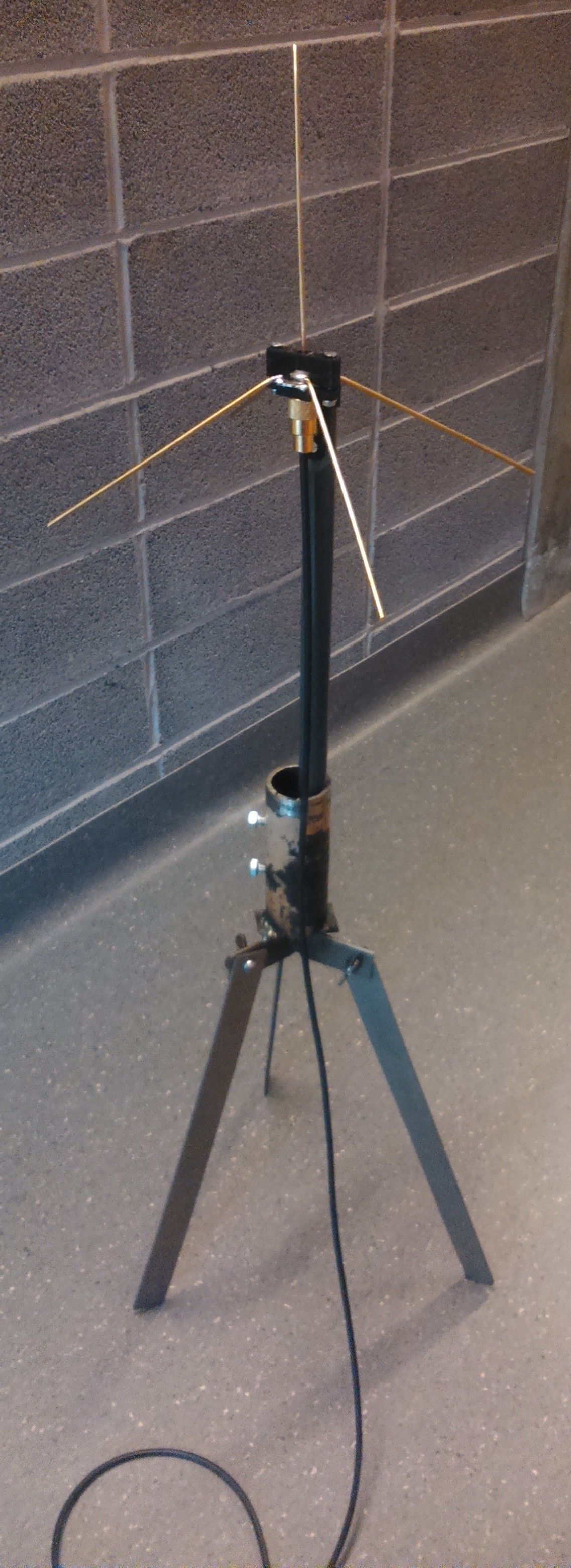
    The support is made of 3D printed PLA, as an effort to try and have as little as possible parasitic metal elements in the vincinity of the antenna. I still have to find nylon bolts and screws to lessen that impact even more.

    The PLA part is attached to a nylon rod which has been milled to ensure a nice mating surface. This rod is also non-metallic as to ensure as little parasitic effects as possible.

    The nylon rod will then be mounted to the actual mast, which I don't have yet.

    The last part, the tripod, was built using scrap metal parts from around the shop. The three legs are held to the central body with three butterfly nuts and lock washers. A piece of pipe was welded on the top of the structure.

  • Waffle Modem Computer Interface

    Frédéric Druppel05/08/2016 at 17:26 0 comments

    While Mano is working on the hardware, I'm working on the software side of the project.

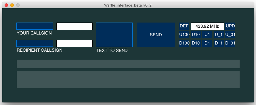
    Today, I designed a raw computer interface for The Waffle using my favorite programming program, Processing. Using the basic ControlP5 GUI library, it was much easier for me to add text fields, buttons, etc.

    You may ask yourself "Why in heavens name did he use Processing instead of stock Python or stock Java ?". Well, there are a few reasons why : because I'm familiar with it, because it's open-source, because it's easy to use and to implement libraries, and also because it's cross-platform, which means that I'm easily able to compile the final program as a ".app" file for OS X, ".exe" for Windows and as an Unix executable for Linux. All that just with a few clicks :)

    Right now, it only works "theoretically". That means that the buttons and the text fields are working (with minor bugs, of course, thanks to Murphy), but it's still the raw interface, it doesn't send the messages over uART yet.

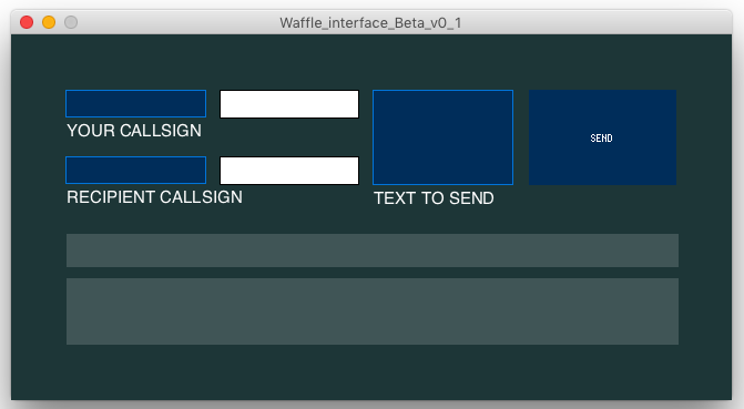
    Here's a nice screeshot on the interface ^^

    As you can see, there are 3 text inputs, 4 text outputs and one button. The two white text outputs are just echoes of the two small blue input fields, the thin grey output field is a preview of the message that will be sent over UART (with the 1st callsign, the second callsign and the message), the thick grey field will be the field where the received message will show up, and the "send" button is, well, the button that will send your message (I shall change the font here).

    I may add other stuff to the interface as we need, but right now these are the fundamental functions.

    If you want to look at my catastrophic code, well, maybe not catastrophic but "uncommented", you can find it at the "files" segment of this project. I will comment the final versions, but right now it is not really necessary as this is only a beta version.

  • Finding a correct name, other uses, parts coming in

    M.daSilva04/29/2016 at 06:54 0 comments

    First parts are coming in. I've sent my order 2 weeks ago... In the meantime, I started thinking about other probable uses for this system. I mean, basically, I made a small PCB with an ATMega328, a small OLED and buttons. Nothing too special, really. The radio module plugs into it, but nothing prevents me to have other uses for it!

    Why not a integrated antenna analyser? I can add a simple DDS chip like the AD9850, an SWR bridge and sample the measurements through the ADC pins of the µcontroller (like this one or that one [PDF alert])! It would be teeny tiny and very useful!The whole thing can just be plugged into the header for the radio module. Plus, as the DDS chip outputs its signal directly to the connector, it can also act as a frequency generator..

    I can also use it as a small voltmeter, with a divider network, some diodes for protection... Not very accurate, but still, it would be pretty interesting...

    Anyway, those add-ons have to wait for the next hardware revision; I still have to find a way to make it portable. Right now it depends on the USB supply to run, not a convenient thing to have if you want to put it in your pocket...

    Also found a name for my project: Waffle. Why Waffle you may ask? Well, I like waffles. A friend found a matching abbreviation for it: Wireless And Free Format Lite Emitter. Feel free to use yours! I'll just stick with "Waffle" :)

  • PCBs

    M.daSilva04/25/2016 at 15:11 0 comments

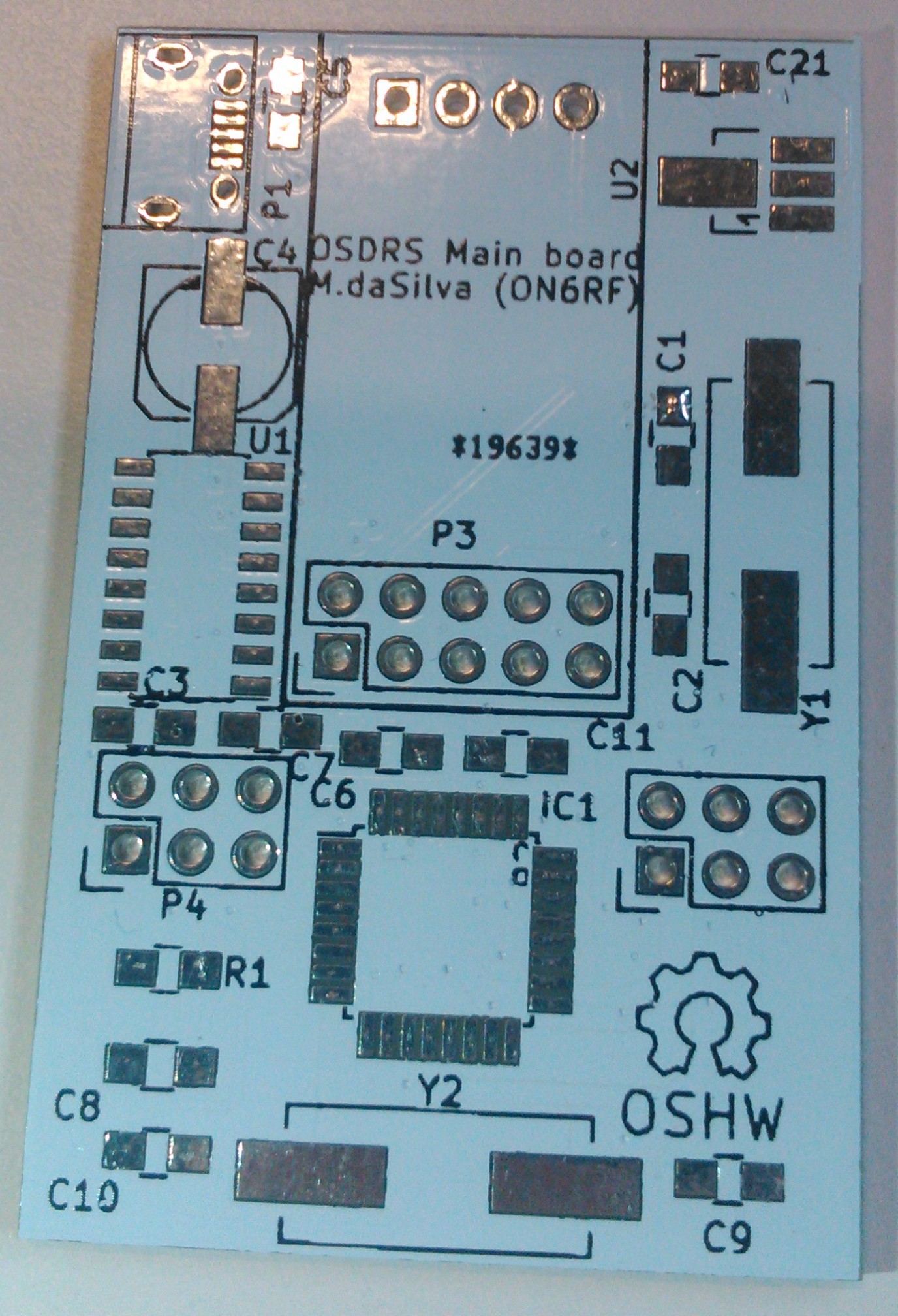
    Just ordered the PCBs from DirtyPCBS!

    http://dirtypcbs.com/order_images/974c28c5b78e50cb8447750d687c1398-19639_top.png

    http://dirtypcbs.com/order_images/974c28c5b78e50cb8447750d687c1398-19639_bottom.png

    I chose to have it in white. I kinda like the looks of it! The "back" side is reversed, I think it's a small bug of DirtyPCBs, I'm not worrying too much, it looked fine on other Gerber viewers.

    The components are also on their way, I hope they won't take too long...

  • Main board design

    M.daSilva04/23/2016 at 07:47 0 comments

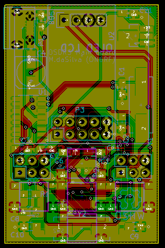
    Sooo... First thing I need to design is the main board. It contains:

    • The ATMega328, with the appropriate crystals;
    • A USB to serial converter;
    • The actual radio module;
    • A small display;
    • Buttons!
    • Supporting hardware for all this stuff (regulators, decoupling caps, crystals, etc.).

    It's your average Arduino-thingy board, the design process is quite straightforward.

    V1.0

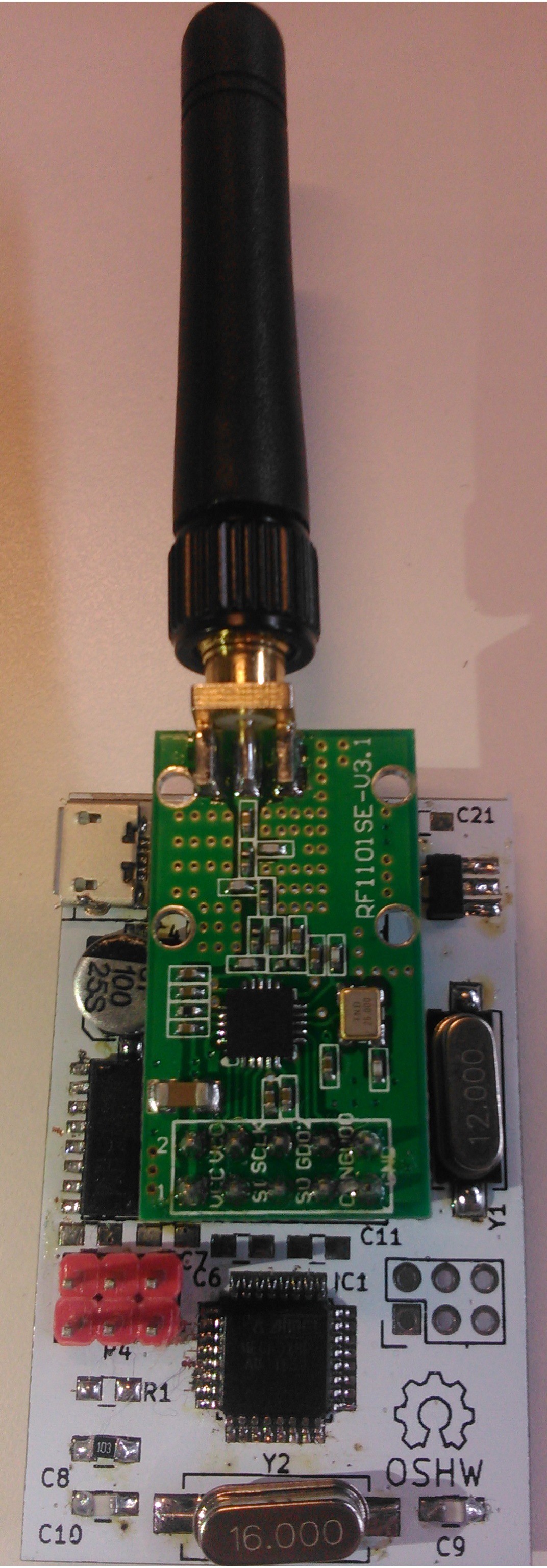
    Small note regarding the RF part: I added all the supporting hardware for the CC1101 on this schematic: the balun system plus all the filters for the 433MHz band. However, I am not going to add this section to the first version: it is my first SMD design, I don't want to add the complexity of RF to this design for now (plus the QFN-20 package is tiny!). I'll use some ready-made modules that will be soldered though a header for now.

    I added 6-pin header for the future PA board; I brought out two IO pins from the µcontroller, 5V and 3.3V power, and ground. RF won't be going through there, I'd rather connect the PA and the radio module through some piece of coax.

    I tried to fit everything onto a 5x3cm board. Phew. Lots of vias, and some traces take a long way to connect one point to another; I'm a bit worried about the USB lines and the crystal for the USB to serial converter, they seem a bit long to me.

    Meh, I'll send it to the fabhouse and see how it goes! Worst case scenario, I'll learn something along the way :)

View all 11 project logs

  • 1
    Step 1
    Those instructions are for the rev 1.0 portable unit, the current prototype I already assembled and tested.

    Preparation

    PCB order

    Order the PCBs from your favorite fabhouse. Everything you need is in SchemBrdDesigns.zip

    I personally used dirtyPCBs; you'll find the zip file I sent in the "gerbers" folder.

    3D printing

    3D-print the three components of the case: the main body, the bottom lid and the D-pad. I used 25% infill, no raft nor supports.

    Components order

    Order the different components. It should be pretty straightforward.

    The CC1101 modules I used came from here: RF1101 eBay. You can use any other module, just make sure they follow the same pin logic.

    The SSD1306 OLED display has to be the I2C version.

  • 2
    Step 2

    PCB assembly

    Solder the components to the PCB, as per the schematics.

    My advice would be to start with the microcontroller side: it's the hardest side to do... Don't forget to solder the radio module header before the display!

  • 3
    Step 3

    Complete assembly

    Insert the D-pad in the main body, check the fit: it should be pretty lose and allow the pad to move up and down easily.

    Slide the main PCB in the case. Finish by connecting the radio module and snapping the lid on the case. Everything should be held tightly, pressing the D-pad shouldn't move the PCB.

View all 4 instructions

Enjoy this project?

Share

Discussions

zyndram wrote 07/22/2023 at 09:38 point

can You add https://reticulum.network/index_pl.html to this system?

  Are you sure? yes | no

Rashen2001 wrote 06/08/2022 at 12:42 point

Is it possible to implement the Tetra network on Arduino? Parsing SDS messages from the TETRA network ? what iron to choose for this?

  Are you sure? yes | no

Erin wrote 06/26/2016 at 15:15 point

I think you're on to something.  I've wanted a device for years now that would be a dedicated texting device that would utilize packet radio.  Something you could solder up using a crystal for single frequency operation.  It would be just for local use where I spend 99% of my time and I'd be able to text any of my local ham buddies.  I've even thought of where you would emulate the mobile phone network but far scaled down where you could have a computer that would receive and save the packets meant for the other person so when they turn on their device, the text message would be sent to them.  If something like this was set up like Echolink, you could have your device anywhere, and it would send and receive texts.  I guess APRS is kind of like that , but to my knowledge it doesn't hold messages and wait for you to turn on your radio.  Basically what it boils down to, is I'd like to have the utter convenience of mobile phone texting, but over ham radio where it would be free.  The major difference between the cell phone networks and ham radio is that cell phones are tracked and ham radio isn't although with the advent of digital radios, the technology is quickly evolving into the convenience of cell phones.

  Are you sure? yes | no

stan.swan wrote 06/25/2016 at 06:51 point

Interesting idea, with niche application, & somewhat in the style of the smartphone/ BT based  VHF text "goTenna" approach =>  http://www.gotenna.com/. Your CC1101 RF IC is no great performer now however, with the likes of  SiLab's Si4463  ( as used in the popular US$3-5  HC-12 transceiver modules)  significantly superior.  

HOWEVER both these  tend  small beer compared with Semtech's UHF LoRa™ offerings, as GREAT range enhancements ( by some 10 times !)  arise if  LoRa™ modules were used.  Yes several km instead of 100s of metees ! See my Instructable for insights =>  http://www.instructables.com/id/Introducing-LoRa-/           73's -Stan. ( ZL2APS since 1967)

  Are you sure? yes | no

hex.online wrote 05/09/2016 at 17:14 point

Hello, regardless of what others could say, I find the project genuinely useful. Allowing text communication without any "man in the middle" and regardless of cell tower coverage.

Some Ideas I have that maybe you find interesting:

- Could it be posible to use an ultra low frequency radio module together with a very resilent communication protocol so that short text messages can be sent very far away regardless of the time it takes to send them?

- I think an interesting use case would be to design a device that has 2 way communication capabilities and that instead of an screen it has bluetooth and can interface with an smartphone app. This would be very useful in disaster situations, for mountain hikers / explorers and for problematic situations where cell towers are saturated / shut down purposely.

- For usecases commented above, and in the case that a screen wants to be added so that even without having access to a mobile device the message can be read, why not adding an e-ink screen so that the message remains visible even when the battery is empty? Adafruid has sme nice little e-ink screens https://www.adafruit.com/?q=e-ink&

BTW, If you want some help designing a metal / 3dprinted case for it, count me on!

  Are you sure? yes | no

M.daSilva wrote 05/10/2016 at 11:57 point

Hi!

Thank you for your comment and your input, I really appreciate it! 

-What kind of frequencies to you have in mind when mentioning "Ultra low"? Sub-30MHz? The aim here is to have a 2 to 10 mile range with those UHF modules, using a very simple protocol with error correction. Reliably counting on the propagation would require big antennas... But why not!

-Bluetooth! Good idea! I'll write it down in the ideas for the next version. This could be offered as an alternative to the OLED display, on the same board!

-You're right, e-ink would be to nice! Having the ability to display the last received message event when the power is cut off is non-negligible. I'll try to look into it if I find a cheap version.

Thanks for the case! Once I get the final mechanical design done, I'll contact you :)

  Are you sure? yes | no

hex.online wrote 05/10/2016 at 12:39 point

Hi, I was thinking on ELF https://en.wikipedia.org/wiki/Extremely_low_frequency or even ULF (goes trough stone - it is used in mines communication systems ) https://en.wikipedia.org/wiki/Ultra_low_frequency

Bear in mind that I am not an electronic engineer so I don't know if for this a 5 meters antena and 2kw of power are needed :) Maybe it is just not fesasible, but my idea is to be able to send and receive data very far awat regardles of obstacles even if it takes 1 minute to send 128 characters.

The idea came to me long ago as I often go hiking trekking to the mountains and cellphone coverage is always bad at best. 

On the other hand walkie talkies (at least the ones I can buy) loose signal rapidly because of a lot of factors (trees, foliage, fog...). And really, often it is enough to send a little message asking for help or giving some gps coordinates.

So I thought it would be wonderful to have a small blackberry like device to be able to send short text messages point to point without depending on cell towers or satellites. 

Then I thought that costs could be saved if it communicated with an smartphone via bluetooth so that screen and keyboard could be spared from the BOM...

Count on me for the case, and congratulations for the interesting project. 

  Are you sure? yes | no

Martin wrote 04/15/2016 at 11:20 point

Pager? We have the 2010er years now. I would not need/want one as I have a smartphone. Perhaps this is nice for experimentation, but not much more. Sorry.

  Are you sure? yes | no

M.daSilva wrote 04/15/2016 at 11:56 point

Heh. I'm doing it for the heck of it. 

Besides, I was thinking something more in the lines of an ham radio emergency notifying system...  Cellphones may be convenient, still they stopped working on march 22 when we had the attacks in Brussels. This is not something we can completely rely on for important communications. An alternative way of notifying hams that they need to deploy "here" or "there" can be useful.

The hardware can be used for much more than a "simple" paging system. Being able to transfer data between two (or more computers) through radio (and not though WiFi which becomes more and more saturated those days) is another idea I had in mind. This is still in the early stages, I'm still thinking about it... For now, I'll just design a board that implements the components and make the first tests.

  Are you sure? yes | no

Does this project spark your interest?

Become a member to follow this project and never miss any updates