 flashcactus
Current state
The board is almost complete, except for some possible refining of the button-debouncing circuit. The software less so, there's still no RNG or satisfactory scaler of the resulting random numbers and the button handler is a work-in-progress. The case also has some problems, although I believe they are more with the 3D printer than with the design of the case.
Design
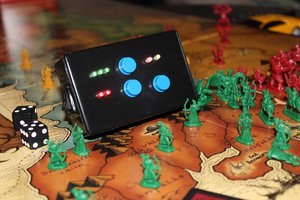
The device uses as its core an Atmel ATTiny13A microcontroller, with one potentiometer and one button as control inputs. The buzzer is the smallest motor I could find with a bit of solder glued onto the shaft. Everything goes into a 3D printed ABS case with dimensions of 30x30x9mm (excluding the strap tabs).
Power
The device runs off a 1225 lithium coin cell , which has a capacity of about 50 mAh.
To save power the μC spends as much time as possible in power-down mode and the μC's ADC hardware is shut down, with all current through the pot is killed whenever not taking a reading.
The resulting power consumption in about 6 μA at 3V, which means about a year of operation on a single battery. In fact the actual runtime would be almost completely determined by how long and how often the motor is buzzed. I haven't made any measurements of that, but considering that one buzz is around 190 ms and the frequency won't generally be more than a couple buzzes per hour, it's gonna be pretty long.
The schematic
The motor is driven pretty straightforwardly, using a 2N7002 nMOSFET hooked up to one of the pins. The other 2N7002 is used to cut off current through the pot when it's not in use, thus using up two more pins together with the pot. One more pin (PB1, since INT0 is there) is hooked up to the button so that it could wake the thing up when pressed.
The board
I used SMD components to keep the device thickness (and also the amount of holes to drill) to a minimum. The only two through-hole parts are the pot and the battery clip. These two also define the dimensions of the board, it could've been somewhat smaller otherwise. It's a one-sided design, which makes it more convenient for home etching. I used photoresistive film as both etching mask and solder mask and a CuSO₄-based etchant. The μC footprint can accomodate both the -SU and -SSU versions of the 'tiny13. Due to the small size of the board, including a standard ICSP header would be impractical, so contact pads with standard 2.54mm spacing (matching the t13-P pinout so that the jig could later be used in breadboards) are provided instead. Ideally the jig/adapter would use pogo pins, but since I don't have those I used sewing needles instead and soldered it to the board for the duration of the development.
The case
Designed in OpenSCAD (partly as a way to learn it). The board is held in place with a slit on one end and a some standoffs on the other. The lid is held by a bolt that goes through the whole thing and screws into a nut held by the lid.
 Scott Clandinin
 Eddie
Eddie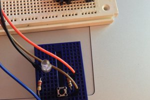
 dougal
 mkdxdx