 DeepSOIC
<Spoiler>
Permeability is about 2. This is hopeless for making motors and the like. Permeability of electric steel (found in transformers) is about 4000, for comparison. Permeability of inductor gap-less core material is typically about 50.
Printing the core
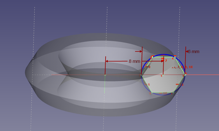
This part is reasonably straightforward. I chose a relatively thin and small toroidal core. Small to not need to spend too much wire for the test coil, thin to not get uneven field distribution through its section, and toroidal because it is very easy geometry to calculate.
I think it's important to choose solid concentric infill. This is because gaps across B-field influence results seriously, and need to be minimized to measure the material properties, not properties of a gapped core. Concentric infill results in a serious gap that slices the core in two rings, but gap is along B-field (not across), so it can easily be corrected for by lowering the cross-section area in calculations.
model parameters:
middle-circle radius R = 8 mm = 8e-3 m
core cross-section area S = 23.38 mm^2 = 23.38e-6 m^2
Making a test inductor
Simply wound a testing coil. It is quite important to distribute the turns evenly, to avoid magnetic field leak to outside and skew the results. Other than that, the more copper - the better chances of achieving saturation.
Here's my winding, I think I did a good job in terms of even-ness.
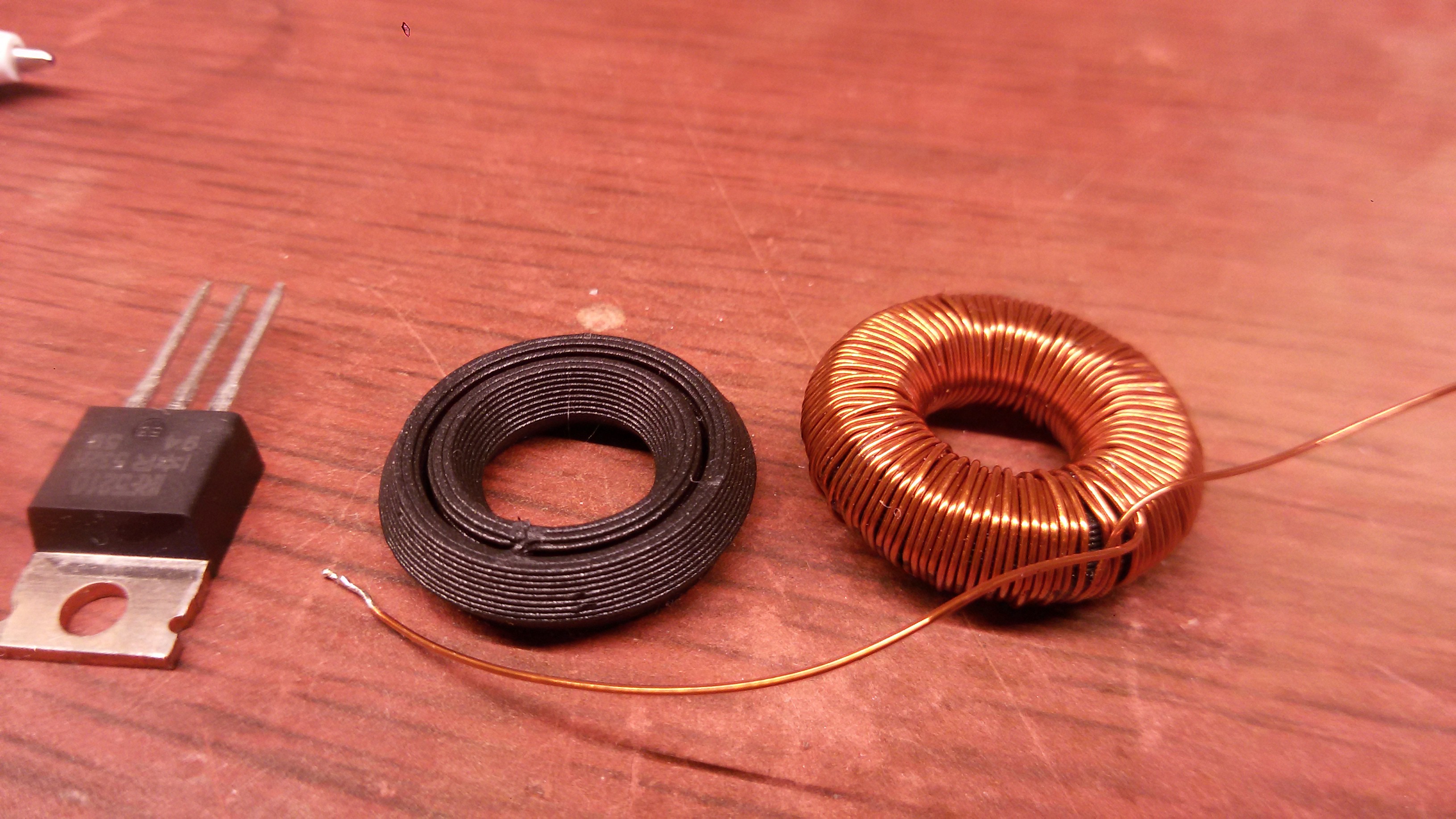 The coil has N = 124 turns. It measures 0.527 Ohms of DC resistance, and has an inductance of 21 uH.
Measuring the inductor
 To measure B-H curve, I drive the coil with square wave generator. I can obtain B field by integrating voltage across ideal part of inductor, and H field by measuring current through coil.
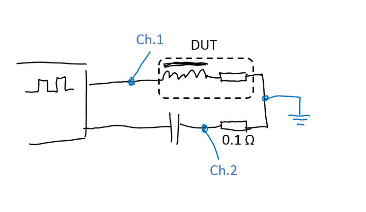
On this circuit:
* to the left is high-current square-wave generator
* DUT is the inductor. I approximate it as an ideal winding around the core (made of superconductor) plus DC resistance of the coil. I assume that skin effect and proximity effect are negligible, since I'm driving it at quite low frequencies (around 20KHz).
* 0.1 ohm resistor is a current sense resistor
* scope probes are connected to points labeled Ch.1 and Ch.2. Scope's ground is connected to the point where the blue ground symbol is (so, the generator MUST NOT be grounded!)
So, on Channel1, I get total voltage waveform across the inductor, and on Channel2, I get an inverted value of current.
* capacitor isolates DC component of square wave from biasing the inductor. The capacitor is a large electrolytic cap. The more - the better.
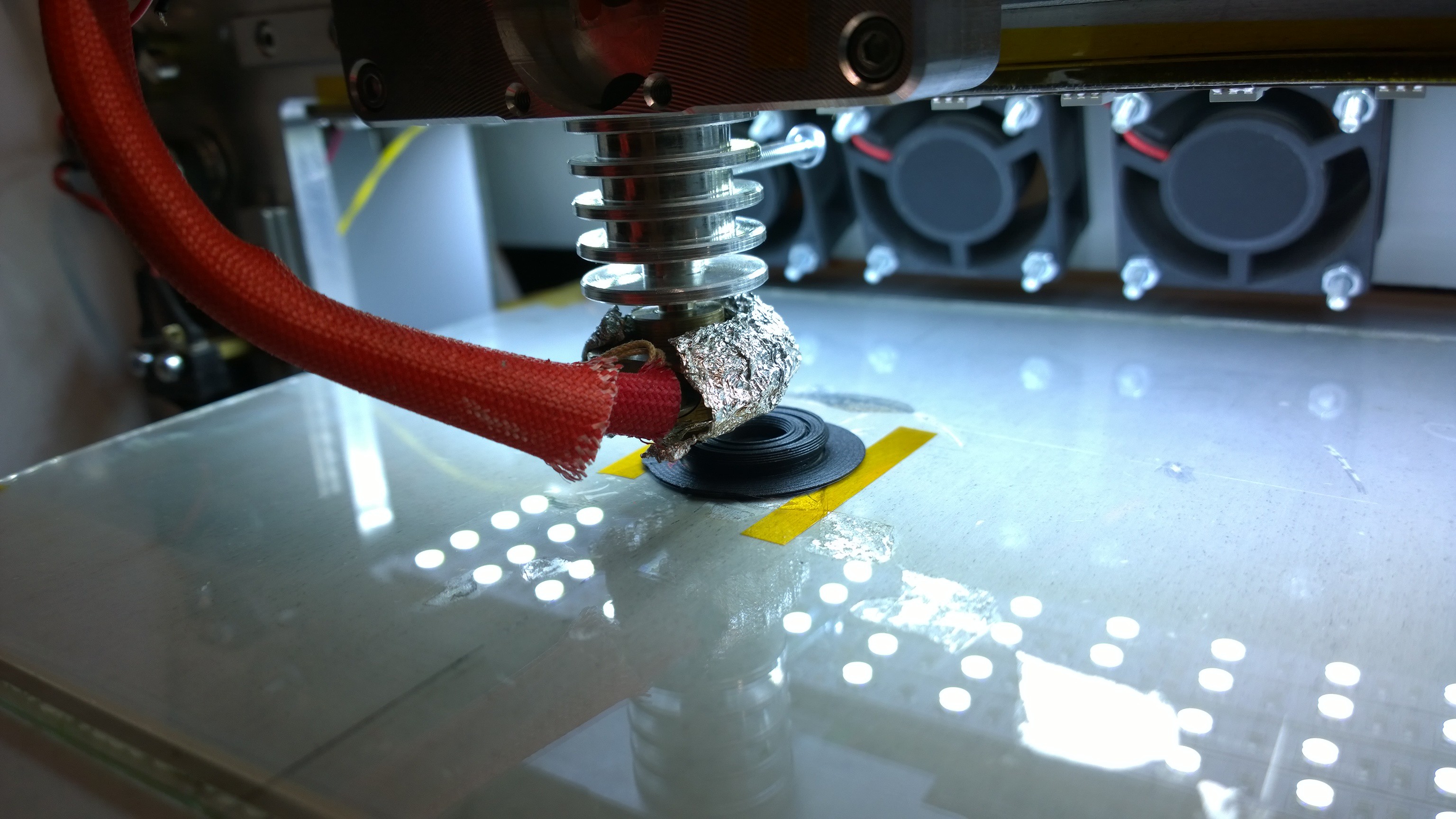
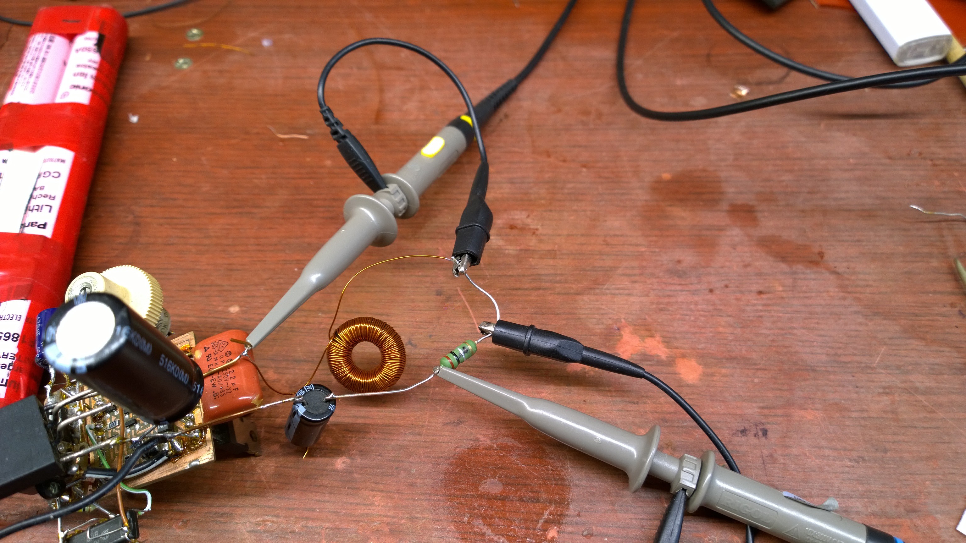
This is how the circuit looks when it's built:
And this is what I get on the scope:
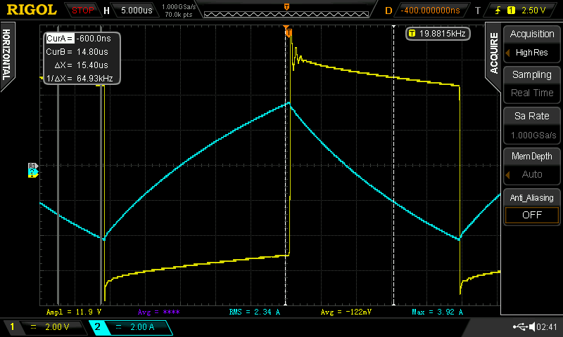
Note that current waveform (cyan) is inverted due to the way probes are connected.
Calculating material properties
H-field
H-field can be directly calculated from coil current by using Ampere's circuital law:
i.e. integral of H-field along a contour equals total current passing through that contour.
Choosing the contour to be the center-circle of the core, we get:
H * 2*pi*R = N * i
where R is radius of core's center circle, N is the number of turns in the coil, and i is the current through the coil. So, H field waveform is:
H(t) = N*i(t) / (2*pi*R)
B-field
Deriving B-field is quite a bit more involved, and that's what I capture voltage waveform for.
Voltage across the ideal part of the coil is tied to the rate of change of magnetic flux by law of electromagnetic induction:
dФ/dt = U(t) / N
where Ф is B-field flux through the section of the coil toroid, which equals B*S assuming B is constant throughout core section area S, and the coil is tight.
U(t) is the voltage across the ideal part of the coil, which can be calculated by subtracting resistance dropout R_DC*i(t) from the total voltage across the real coil:
U(t) = U_real(t) - i(t)*R_DC
So,
B(t) = integral over time( (U_real(t) - i(t)*R_DC) / N ) / S + offset
'offset' is a constant, that should be chosen so that time-averaged B-field is zero.
Results
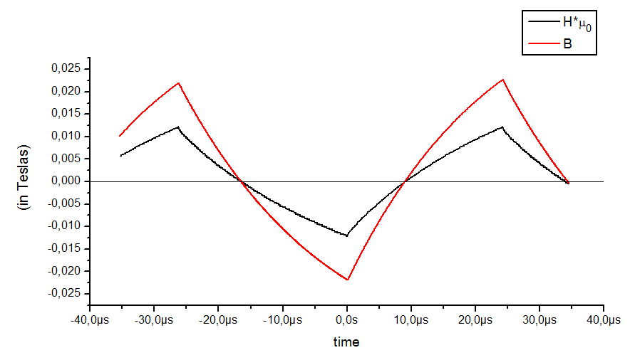
On this plot, B and H field wavefoms are shown. H was multiplied by permeability of vacuum mu0, to bring it into a comparable scale with B-field. The ratio of B/(H*mu0) is the permeability of the core.
And if I plot one against the other, I get this:
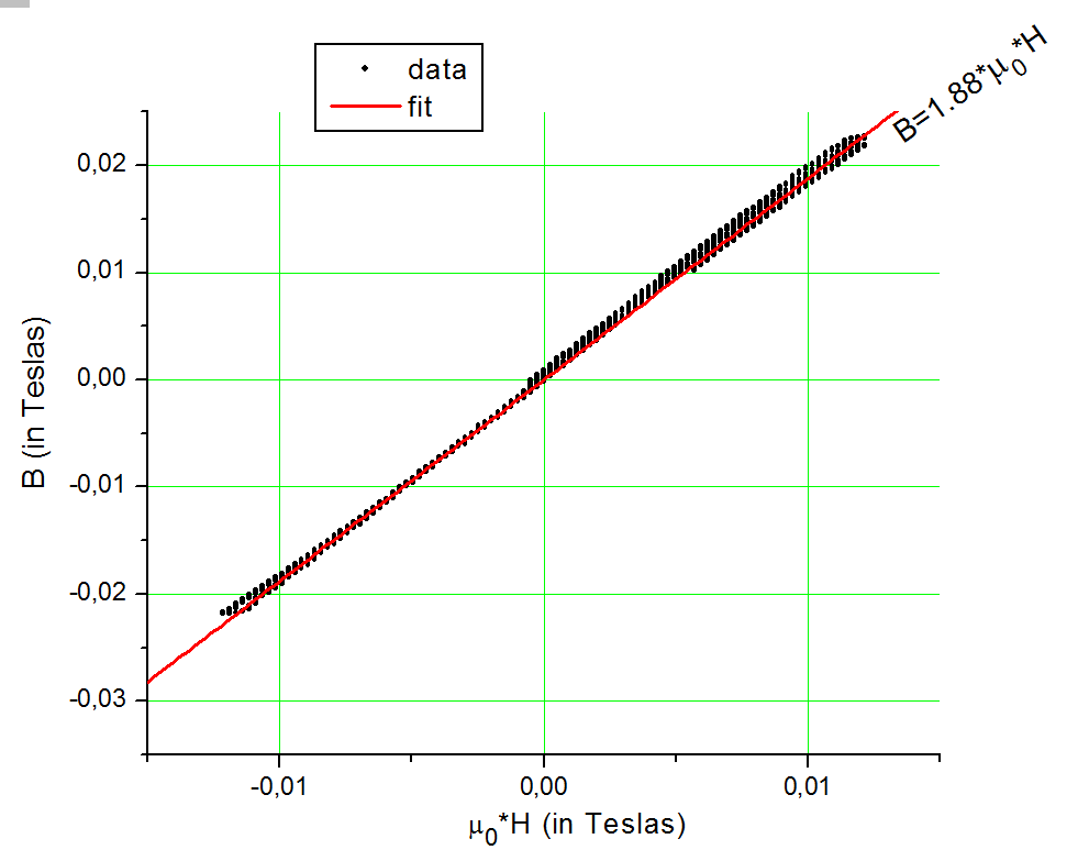
So.
Permeability is about 2. I didn't introduce any corrections to area, so the value may be off by about 20%, but that's a good enough result to say:
BlackMagic3D's ferromagnetic filament is NOT SUITABLE for making transformers, motors, inductors, electromagnets, and other stuff with magnetic circuitry. This is because for the magnetic field to be preferentially flowing through a material, its permeability needs to be way more than that of vacuum. 2 times is NOT way more. I consider a value of 10 to be the threshold of a material becoming interesting.
I failed to achieve saturation of the core due to its very low permeability. I need ridiculous amount of copper to achieve it, which will void some of the approximations made in calculations. I won't bother obtaining saturation flux, it is simply unreachable in practical situations.
The loss is low, which is probably due to the amount of non-magnetic material (PLA) in the core, which is basically like loss of vacuum, very low. My test inductor is like an inductor with a very large gap in core.