 robert.c.baruch
The software is based on the GNU MPFR library (Multiprecision Floating Point with Rounding), using a precision of about 200 digits (665 bits). When displaying such high-precision numbers, you can use a paddle switch to "scroll" the display 20 digits left or right.
0%
0%
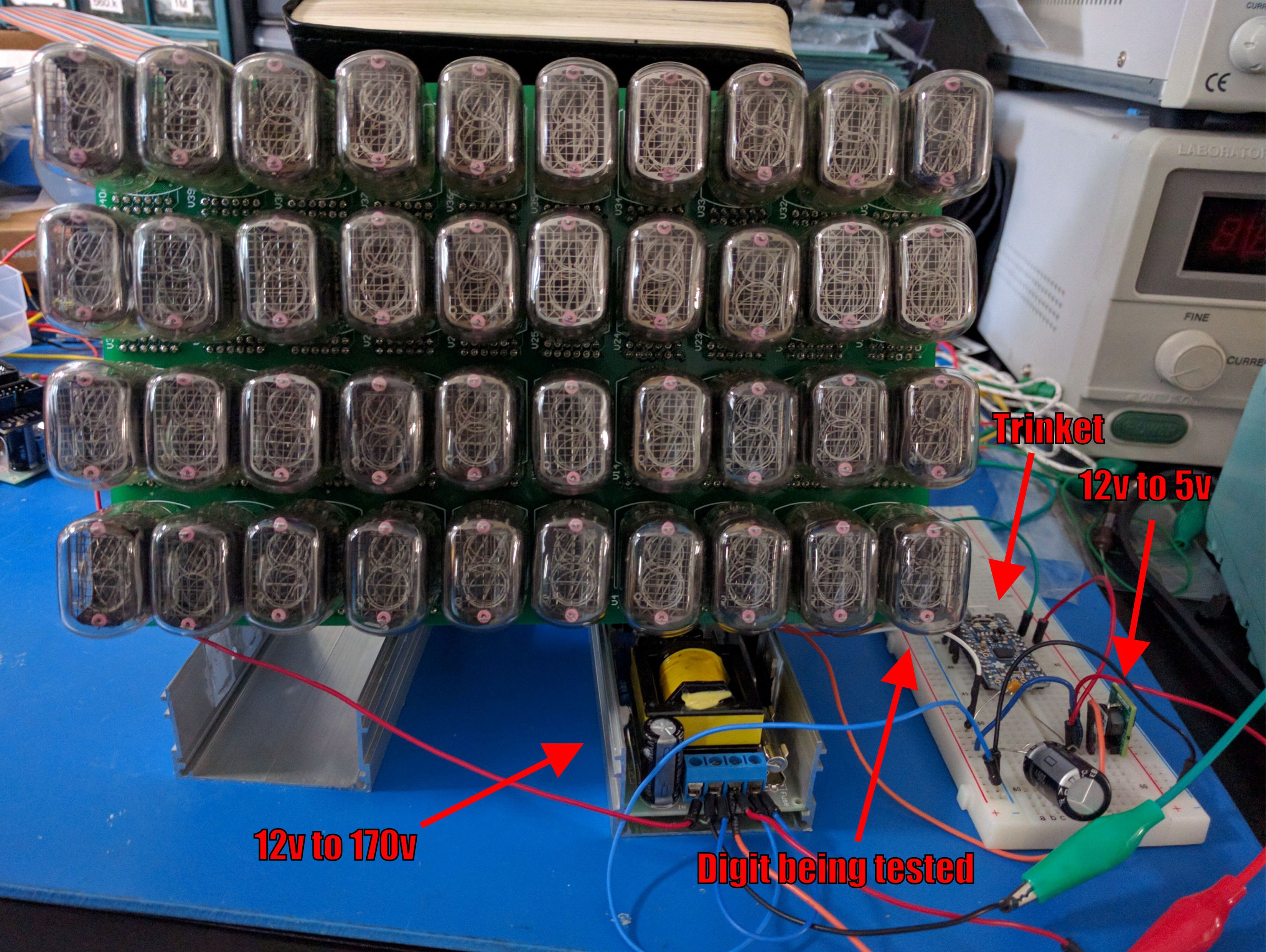
RPN Nixie Calculator
A programmable RPN calculator using way too many Nixie tubes
Become a Hackaday.io member
Already have an account? Log in.
Just one more thing
To make the experience fit your profile, pick a username and tell us what interests you.
Pick an awesome username
hackaday.io/
Your profile's URL: hackaday.io/username. Max 25 alphanumeric characters.
Pick a few interests
Projects that share your interests
People that share your interests
 Yann Guidon / YGDES

 Paul Andrews
 hamster
Hey, Can you help to create the similar tool for my DLL project? You I'm already working on it but need little help, you can see here detail https://fix-dll-errors.com/dll_files4.dll.php