 Johnson Thie
1. The challenge
Devices to acquire electrical activities of the heart (ECG) and electrical activities of the muscles (EMG) have usually been used to diagnose diseases and assess treatment effectiveness. Only large institutions and hospitals can afford them since they are expensive, partly due to the lengthy and costly approval process.
The challenge is to develop a low cost (< $50) 1-channel ECG/EMG device with the following features:
- readily interfaced to a computer or mobile device for real-time analysis,
- the analogue front end circuit can be modified,
- the ADC can be reprogrammed
Recent advances in technology have reinvented the devices for fitness and general health purposes. Hence, they do not need to be approved as medical devices for diagnosis or treatment. Given the popularity of mobile technology, they have been packaged with wireless technology, such as Bluetooth, or integrated with mobile devices. One example is Spyder, a wearable device, that not only records and stores ECG but also transmits it to a mobile device via Bluetooth. Another example is AliveCor which is an attachment to an iPhone and transmits ECG to the iPhone via Bluetooth when its pads are placed on the chest. Spyder and AliveCor costs S$500 and US$99, respectively. These devices offer developers none to limited access to the hardware and rely on wireless technology, hence higher price tag.
In addition, Vernier EKG sensor outputs analogue ECG signal that can be interfaced with acquisition devices (e.g. National Instruments acquisition units) or low cost microcontrollers (e.g. Arduino). Vernier EKG costs US$200.
Recently, EMG front-end analogue board, MyoWare, is available from Sparkfun for only US$38. Both devices require a microcontroller and so offers customisation by the user.
Educational and research institutions have also explored low cost ECG/EMG devices [1]–[6]. Some have become commercial products though the price was in the range of hundreds of dollars. However, most of the work have not gone further beyond prototypes into commercial products.
2. The Significance (what problem this challenge will solve)
The key significance is that schools and universities can afford to deploy many ECG/EMG devices in classrooms. In fact, this idea arose from the need to have 50+ EMG/ECG devices for use in biomedical engineering class.
In classrooms, students can learn the physiology of muscle and heart by observing and analysing their own ECG/EMG in real time. It is possible for students to borrow the device for a long term to conduct a project or even buy the device for themselves.
Hobbyists and developers can learn ECG/EMG and develop apps to improve fitness and general health by analysing the ECG/EMG. Novice hobbyists can hack the front end electronics to acquire the brain and eye electrical activities (EEG and EOG respectively). More advanced hobbyists can incorporate a high frequency current source to measure impedance of a part of the body, for example, to estimate the lung volume during breathing and the amount of blood pumped by the heart.
3. Design
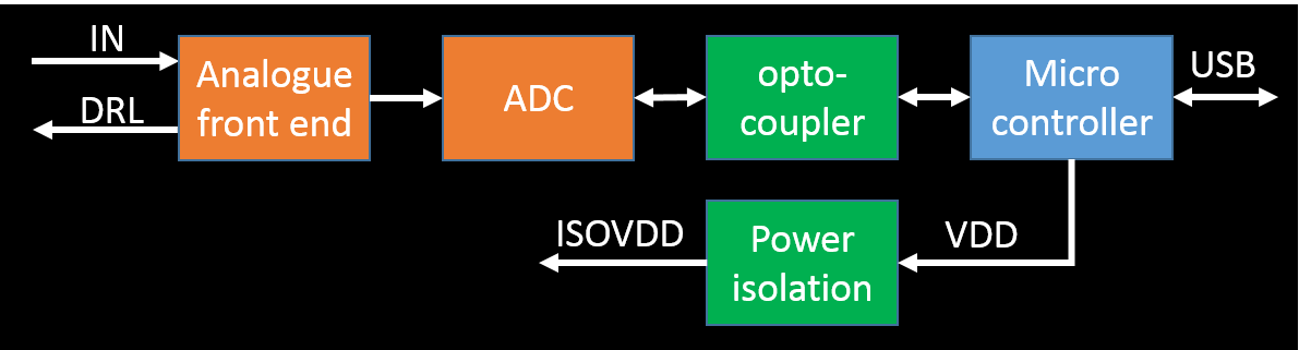
The "conventional" design of an electrophysiology device is shown below.
3.1. Design constraints
- Input signals:
- EMG: the amplitude and frequency range from 1 to 30 mV and from 5 to 30 Hz, respectively.
- ECG: the amplitude and frequency range from 0.1 to 10 mV and from 0.5 to 40 Hz, respectively.
- Sampling rate: 10 x max frequency of the input signal = 400 samples/second.
- Amplifier gain:
- Using a 24-bit ADC with ENOB = 22 bits, the resolution is 5V/(2^22) = 1 uV/LSB
- Hence, no amplifier is needed.
- The ADC must have at least 1 differential input.
- ADC with built-in PGA or ability to add an amplifier
- Current consumption of the isolated circuit: max 100 mA
- Optocoupler with at least 3 channels for clock, input and output data
- Small footprint and low cost
- USB connectivity
| Section | Requirements | Design constraints |
| Analogue front end | Gain = 1 (option for gain > 1) | 3, 5 |
| ADC | Differential input | 4 |
| Optocoupler | 3 - 5 channels | 7 |
| Power isolation | Small footprint and low cost | 8 |
| Microcontroller | Small footprint | 8 |
3.2. Analogue front end design
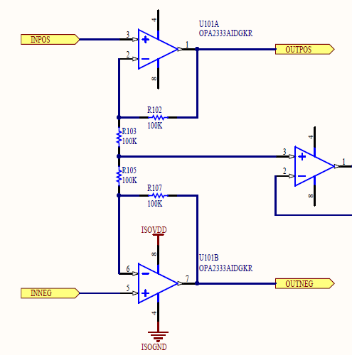
The analogue front end circuit only needs buffers since amplifier is not needed. However, the buffers will be designed as non-inverting amplifiers with low gain and low pass (anti-aliasing) filter. They will also obtain and feed the common mode voltage to a driven right leg circuit.
OPA2333 will be used for the non-inverting amplifiers. OPA2333 is a precision operational amplifier with low noise, low power (17 uA) and small offset voltage (max 10 uV).
The figure below displays the schematics of the non-inverting amplifiers. The gain is only 2. The low pass anti-aliasing filter can be implemented by placing a capacitor on the feedback resistor. The capacitor is not shown in the schematics but can be placed on top of the feedback resistor, hence occupying the same footprint as the resistor. A capacitor value of 33 nF will produce a 3-dB frequency of about 50 Hz.
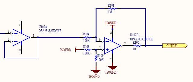
The schematics of the driven right leg circuit is shown in the figure below. Currently, it uses OPA2333. However, since the circuit does not need to have high precision, it may be replaced with a different opamp with lower cost while matching the footprint and pins, such as, TLV2333.
3.3. ADC design
| ADE7912 | ADC1252 | ADS1220 |
| Built-in signal and power isolation | No isolation | No isolation |
| Internal reference 1.2 V | External reference | Internal reference 2.048 V |
| External clock 4.096 MHz | External clock | Internal clock |
| VDD = 3.3 V | VDD = 5 V | VDD = 2.3 – 5.5 V |
| No PGA | No PGA | PGA = 1 – 128 |
| 1 pseudo differential input | 1 differential input | >= 2 differential inputs |
| 20-pin wide SOIC | 8-pin SOIC | 16-pin TSSOP or QFN |
| ~$17 | ~$10 | ~$14 |
ADE7912 is an attractive option due to its built-in signal and power isolation. (Individual signal and power isolation parts have large footprints and height.) However, it lacks PGA and differential input.
ADS1252 is a “bare bone” ADC and has low cost. However, it lacks many essential features including PGA, reference and clock. Adding these parts will increase the footprint and cost.
ADS1220 is the best compromise among them. It meets all the essential requirements outlined in Section 3.1 though it lacks the signal and power isolation.
3.4. Optocoupler design
The optocoupler is used to transfer the digital signals from the ADC to the microcontroller. The optocoupler transfers
- SCLK and DIN from the microcontroller to the ADC
- DOUT from the microcontroller to the ADC
- Optional DRDY from the microcontroller to the ADC, since some ADCs’ DOUT also acts as DRDY.
- Optional CS from the microcontroller to the ADC. Alternatively, CS can be asserted to LOW.
Therefore, the optocoupler must have at least 3 channels with 2 channels in one direction and 1 channel in the other direction.
3.5. Power isolation design
The power isolation section converts the 5V supply and ground from the microcontroller to another 5V supply and ground which are electrically isolated. The key reason for the isolation is that the microcontroller’s 5V supply and ground could be powered from the mains supply which then may contain 50/60 Hz component “leaked” from the mains.
R1SE-0505 from RECOM POWER is used to convert the 5V supply. The maximum current of the isolated supply is 200 mA and it has the lowest cost of about $3.
3.6. Microcontroller design
The microcontroller must have a small footprint, direct USB connectivity and SPI port. It does not need to have low power since it is powered through USB.
4. Prototype development
The initial prototype will be developed in May after all the parts arrive.
References
[1] N. Lovell and B. Celler, “CARDIOSYS - A LOW COST SYSTEM FOR THE ACQUISITION, ANALYSIS AND DISPLAY OF ECG DATA.,” Australas. Phys. Eng. Sci. Med., vol. 10, no. 4, pp. 207–213, 1987.
[2] Z. Blazek and J. Janecek, “Low-cost microcontroller driven ECG,” J. Microcomput. Appl., vol. 17, no. 3, pp. 311–315, Jul. 1994.
[3] R. Isais, K. Nguyen, G. Perez, R. Rubio, and H. Nazeran, “A Low-Cost Microcontroller-based Wireless ECG-Blood Pressure Telemonitor for Home Care,” in Annual International Conference of the IEEE Engineering in Medicine and Biology - Proceedings, 2003, vol. 4, pp. 3157–3160.
[4] B. A. Walker, A. H. Khandoker, and J. Black, “Low cost ECG monitor for developing countries,” in 2009 International Conference on Intelligent Sensors, Sensor Networks and Information Processing (ISSNIP), 2009, pp. 195–199.
[5] G. Singh, V. Gupta, A. K. Sekharmantri, A. Gupta, P. Kumar, R. B. Patel, and B. P. Singh, “Real-Time Online Monitoring of Electrocardiogram (ECG) using Very Low Cost for Developing Countries,” in AIP Conference Proceedings, 2010, vol. 1324, pp. 251–254.
[6] D. Sarkar and A. Chowdhury, “Low cost and efficient ECG measurement system using PIC18F4550 microcontroller,” in 2015 International Conference on Electronic Design, Computer Networks & Automated Verification (EDCAV), 2015, pp. 6–11.