 Walt Perko
Anybody anywhere in any language around Earth and beyond can learn the fundamentals of manufacturing learning some basic electronics and completing the circuit on a real circuit board that can be used in almost any project you can dream up using almost any computer chip or module you want to use for your project. Then learning the BASIC language and c language programming while your 3D plastic parts are printing you learn about different components, sensors, motors, how to program using phonemes to have your project talk back to you in your own language be it English, Japanese, Chinese, Hindu, beeps 'n pops 'n clicks etc...
Programming lessons show how to write library functions and use them in structured programming style so you learn how to program at the highest quality programming style that makes programming projects so much easier.
Finally, after the 3D plastic parts are printed you learn how to finish the parts, trimming and painting then assembling the projects so you learn how to design for 3D printing and easy assembly of new projects you dream up later.
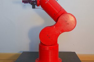
 AngelLM
 Mike Szczys
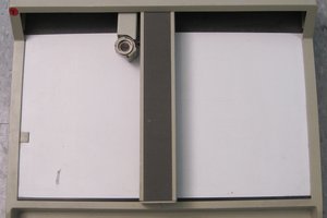
 Owen Trueblood
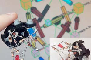
 Anderson Antunes