 kirrent
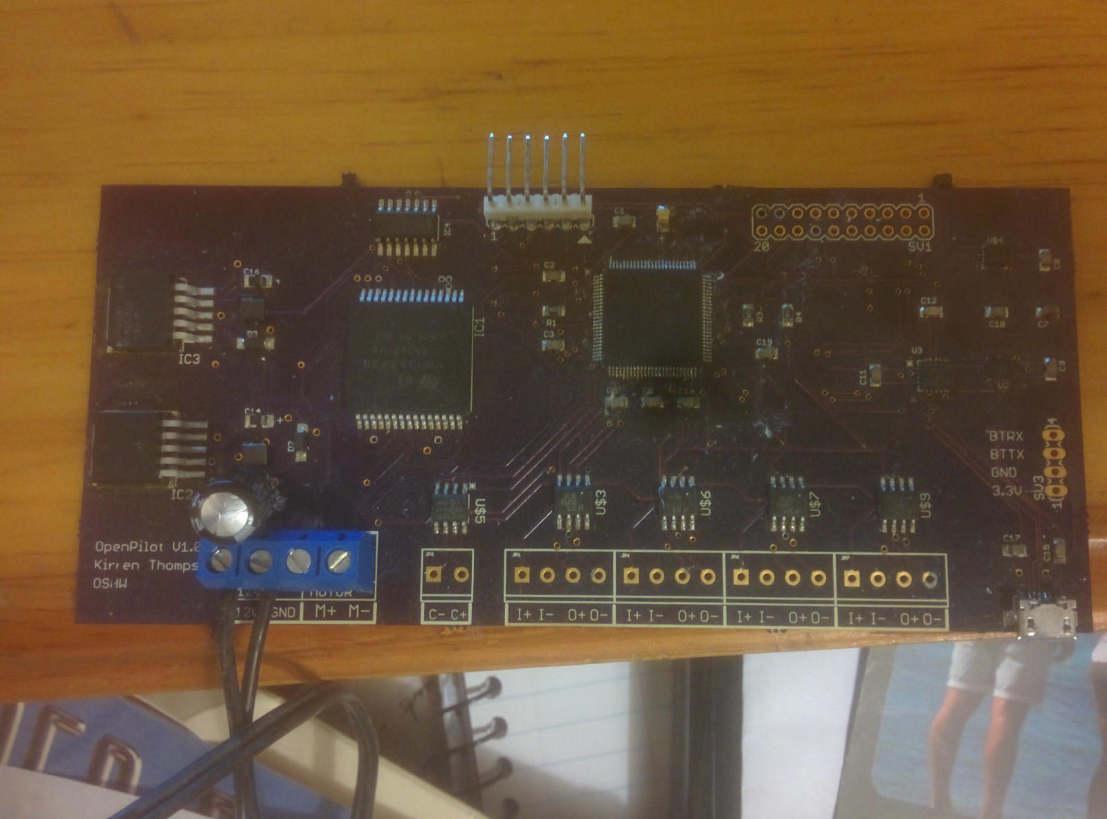
Any complete redesign of a project needs a good understanding of what went right and wrong the first time. The board is above so I'll be working across the thing from left to right in the absence of any better ordering that comes to mind.
While designing I imagined the board being used to power other devices but it turns out there's not a lot of situations you need to supply another device with 3.3V or 5V. As a result it turned out the regulators were super over specced. If you're only powering a small amount of logic then there's also little need to use switching regulators which are more expensive and require more components exterior to the regulator. There's plenty of money, space, and hassle to save by switching to less powerful linear voltage regulators. There's also only a few of components that needed the 5V power supply. The motor driver I was using and any HD44780 lcd I could find. As it turns out, there's 3.3V replacements for both that are pretty easy to find (love that 5110 lcd) so if I can find a couple of more alternatives I could do away with the 5V rail.
The screw terminals? Love the screw terminals. They're an excellent compromise between a permanent setup and switching out different components. Considering they're used on a lot of autopilots I won't fix what ain't broke.
The all in one H bridge is a brilliant piece of tech. For simplicity's sake I certainly think it's worth the money especially seeing as alternatives wouldn't be that much cheaper. I'll be substituting the 3.3V version and expanding the driver's thermal pours. The datasheet claims a 30A max continuous current but the rating is entirely dependent on heatsinking. I want to be able to have the autopilot capable of 10A but I guess if you want more a heatsink might work depending on the thermal conductivity to the top of the package.
The RS422 drivers worked well, unfortunately all the other marine electronics in the world doesn't necessarily adhere to the standard properly. An NMEA0183 fact sheet warns that non-comformant devices with differential voltages up to 15V are common enough. I'm sure there's some silicon out there which can help.
CAN works just fine. All the difficulties here are on the software side.
I hated the microcontroller. I appreciate most things about the hardware itself. It's got great peripherals, must be pretty hardy considering how dodgy my soldering was, and I'm used to PICs. Unfortunately, the lack of good software from Microchip is even more noticeable now I'm using a 32 bit processor with so many peripherals I want to use. Harmony looked promising but it turned out to be quite painful and the C toolchain is still terrible.
I've been playing around with some STM32 stuff using the GCC compiler and been enjoying the cube stuff so I'll be leaving my old love Microchip behind and moving to ST. I just can't follow them into 32 bit.
Finally, I used a separate accelerometer and gyro for slightly higher accuracy and precision originally. Turns out that I really didn't need that so I'll be using a sensor where the two are integrated. On the compass side, things are great and work well once you've swung the lead.
Discussions
Become a Hackaday.io Member
Create an account to leave a comment. Already have an account? Log In.