 Chuck Glasser
The DIY Space Grade PCB is the first of 5 projects that comprise my entry to the 2016 Hackaday Prize. The ultimate goal for this very involved project is to demonstrate my solution to one of the most difficult problems in all of engineering, that of producing a fully functional and field operational Neural Interposer, Gibson's Cyberspace Deck, aka Brain Machine Interface, not surprisingly it also makes a very capable device for Molecular Biology.
Project 1 outlines the ceramic PCB process.
Frequently I find that the problems I like to work on require very complex PCBs with buried and hidden vias and even vias in pads. With vias in pads comes 3 mil lines. Just for fun lets make it a 12 layer board. To find a manufacture of such a board my choices are now reduced from hundreds perhaps thousands of board shops around the world to a countable handful. The cost of a single prototype went from a few $ per square inch to many hundreds of $. I could expect to pay several thousand $ for just a few boards with a lead time of several weeks. Well, one thing is certain, I'm not going to pay a board shop thousands of $ for something I can do myself!
OK, if it's so great why isn't it used more often? The answer is shrinkage. When ceramics are fired there dimensions change. There are ways to keep the shrinkage under control but they are uneconomical and expensive in volume so typically 99.9999% of the time FR4 will do.
At least for now, I'm content to know that the technology of LTCC can provide the boards I need. I don't expect to get to the highest levels of performance immediately, but I know they are obtainable. That's why it's called the art of the hack.
The ability to fabricate circuitry with high tolerance is limited by the precision of the mechanical components of the system, the stiffness of the structures, vibration control, step size of the stepper motors, pitch of the screws, and many 2nd order effects.
To reach the goal of producing multilayer PCBs it's first necessary to place vias in the material, deposit ink within the holes, and lay down as many layers of silver ink as necessary to reach the desired conductivity.
Rather than use multiple machines for these operations I've elected to build one machine. I call it a 3-D fabricator.
My 3-D Fabricator is a big project. It sucks up money, time, and resources like a black hole. I even remodelled a room in the house just to hold it.
3D FABRICATOR
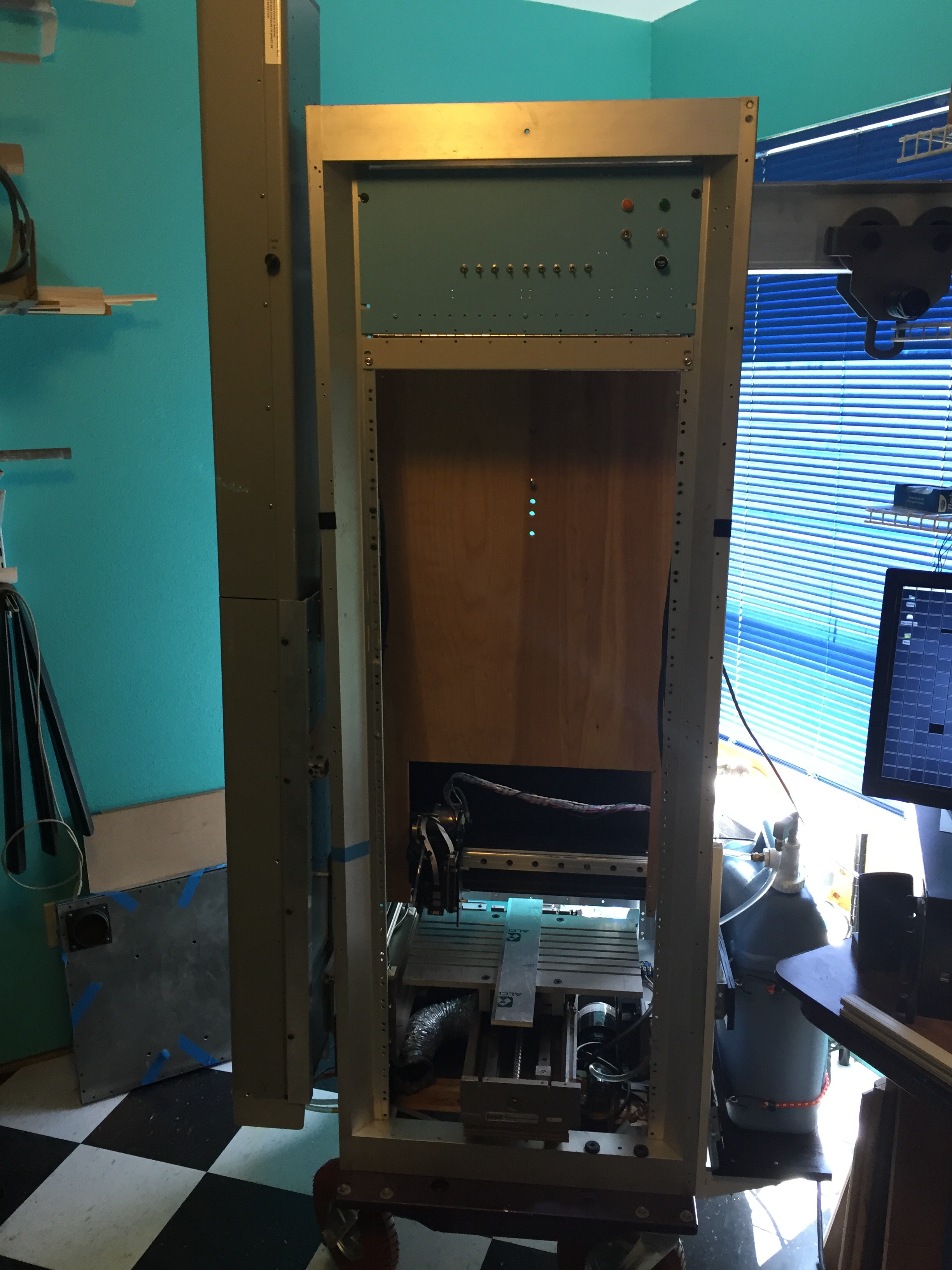
Except for the instrument rack that I've had for decades the other major pieces of hardware, like the laser on the left side and the X and Y traverses have all come from EBay. Just below the slotted bed on the left you can see an air exhaust hose and on the right, a water pump and radiator for cooling the laser, the blue container is the water reservoir for the cooling system. Just above the slotted bed is the X axis traverse with a multifunction tool head that has a laser focus assembly, and ink jet printer head, camera and Z axis traverse along with an Arduino and a BeagleBone Black. This assembly is called the short bed. The plywood above that is a mechanical mock-up that duplicates the basic mechanical dimensions of the "long bed" that weighs several hundred pounds.
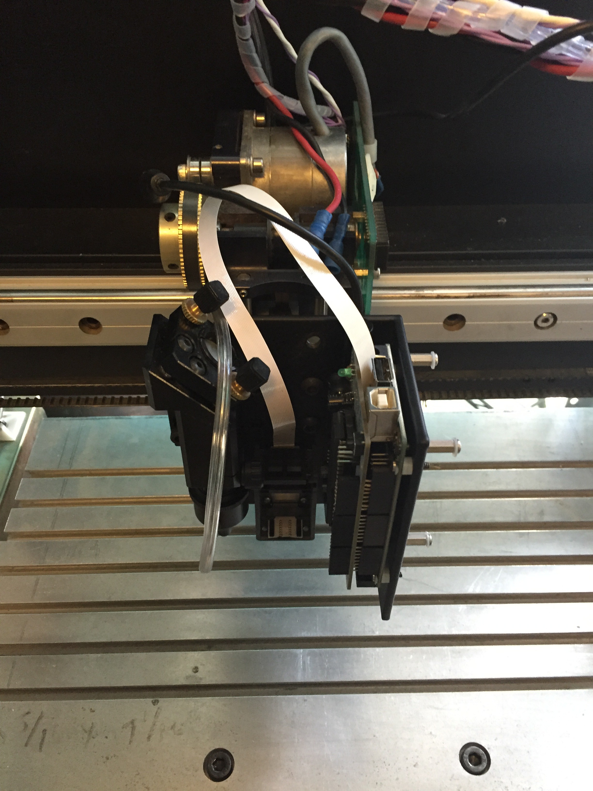
A closer view of the laser/printer head. The plastic hose supplies a constant source of air or an inert gas for protecting the optics. In the center is the print head assembly and further to the right the camera hidden from view along with the Arduino. The Beaglebone Black is dismounted.
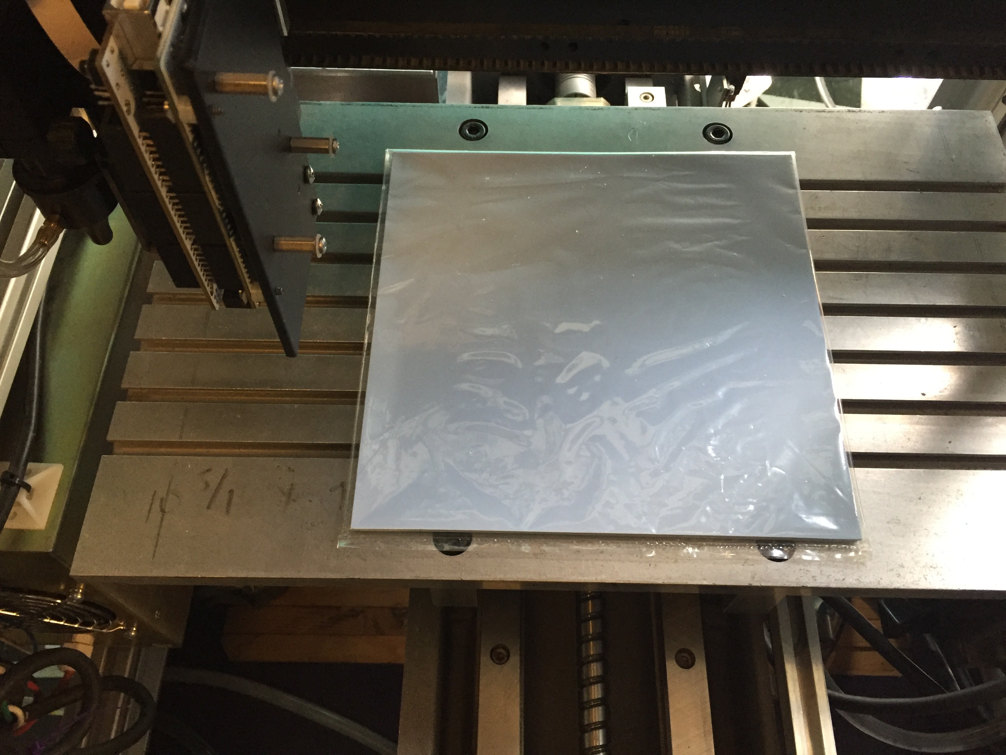
For illustrating scale, here is a stack of "green tape", the ceramic material of interest. The material is from Hereaus. Each sheet costs about a dollar per square inch. The ink comes from ElectronInks.
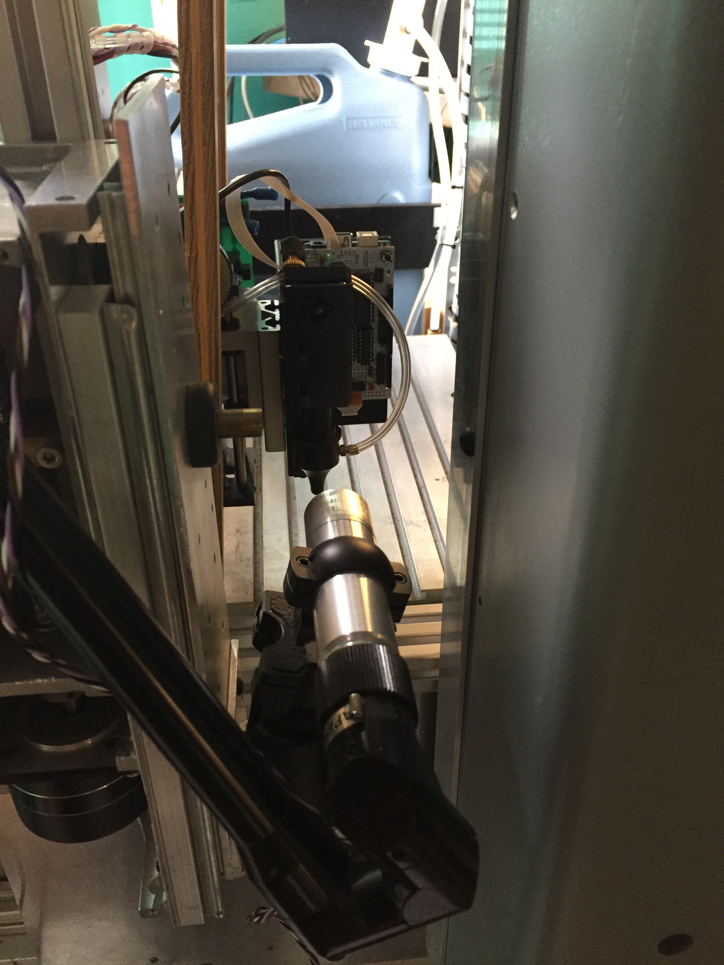
This is the working end of the laser articulation. It takes 8 mirrors to get the beam down to the work. The assemly to the left is another stepper that controls the Z-axis elevation of the laser so that it tracks the z-position of the main tool head located on the short bed.
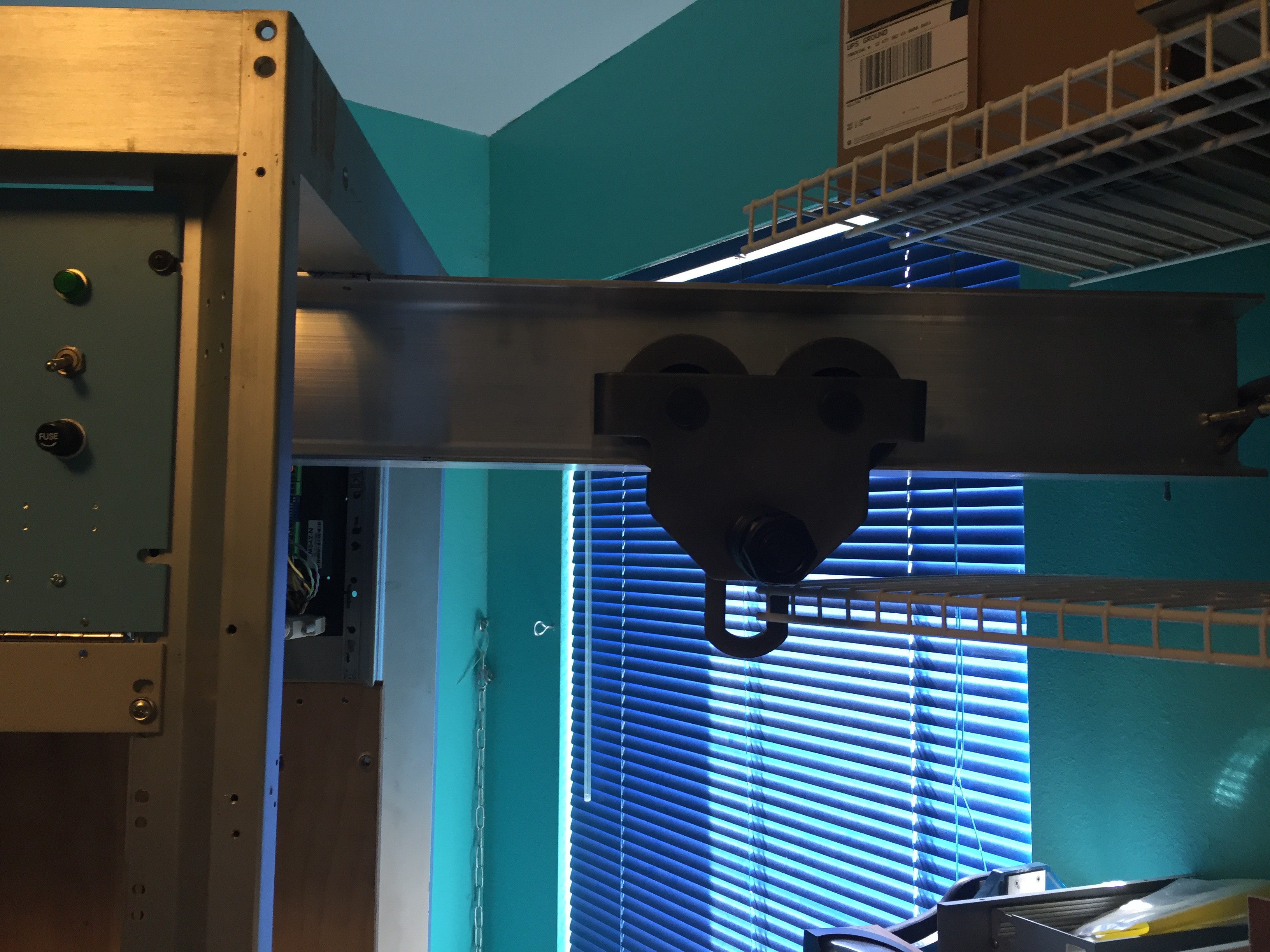
This machine is so big that it has a gantry for lifting assemblies.
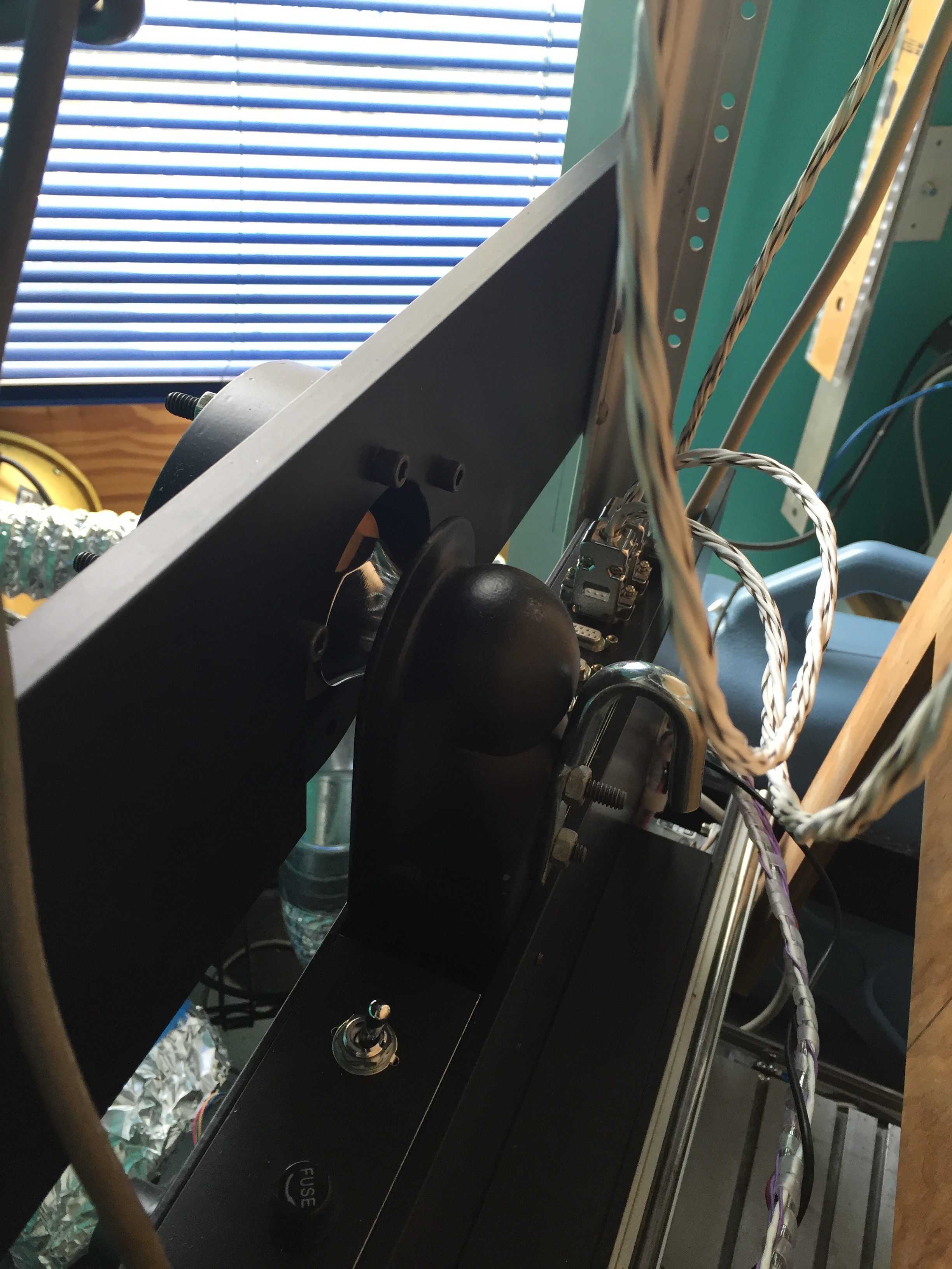
Your eyes are not deceiving you. That's a trailer hitch re-purposed as an optical mount. It makes the operation of holding, lifting, and moving heavy assemblies safe and effortless. Roll, pitch, and yaw are easily adjusted with just 3 precision 100 turns/in screws.
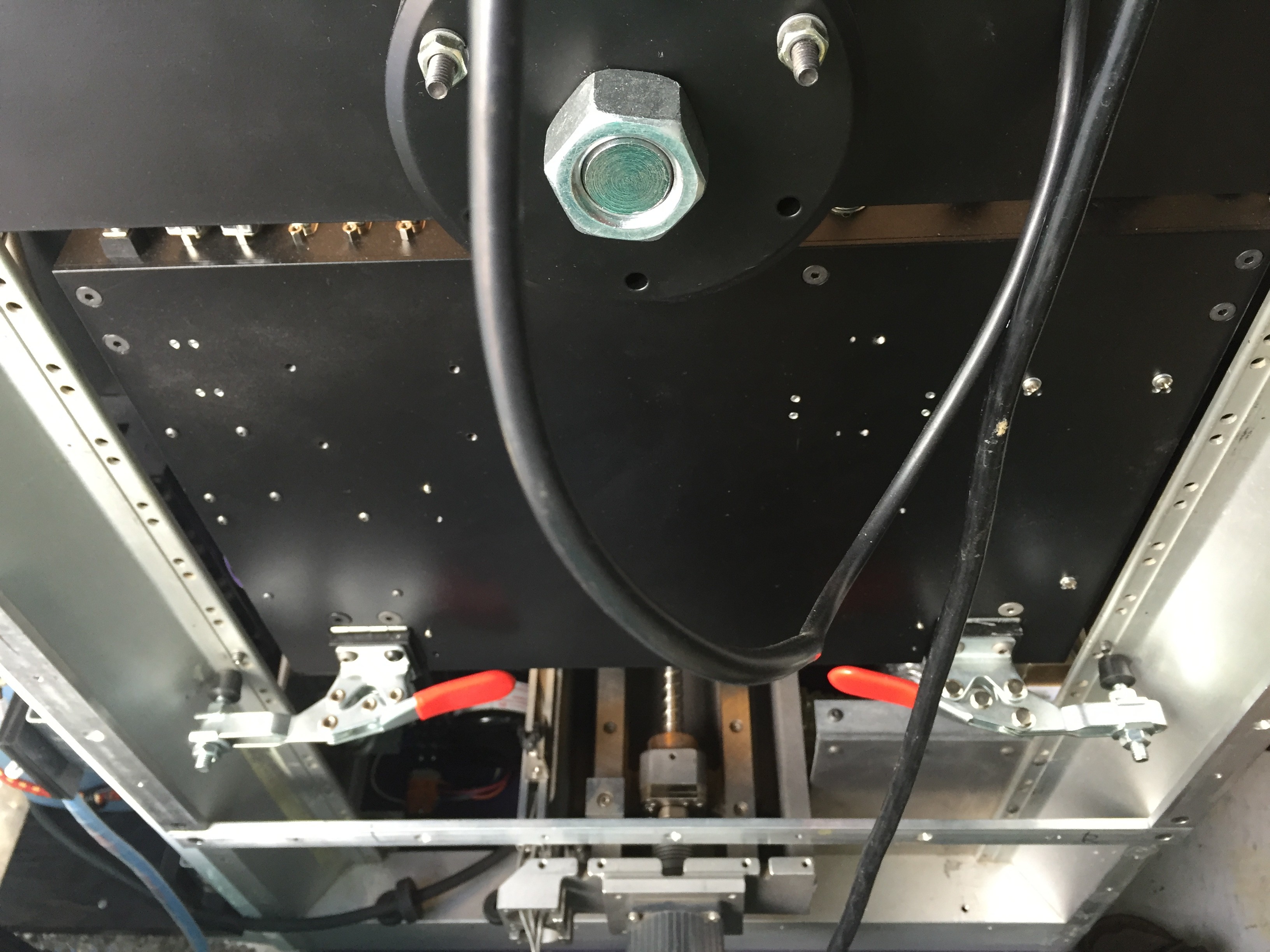
These are the pitch and yaw hold downs that exert about 500 lbs force each. When they are engaged, nothing moves.
LinuxCNC is used for controlling all the various servos and steppers within the machine. The BeagleBone Blacks run MachineKit. I'll discuss the software more in Project 4.
ISOSTATIC PRESS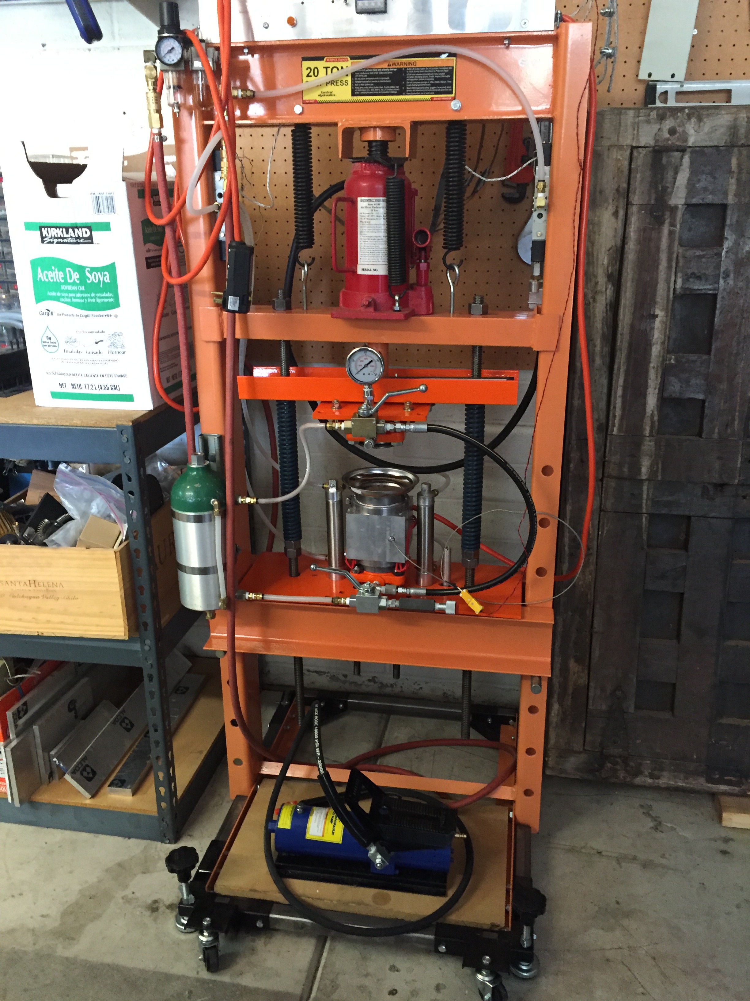
After the various layers of green tape have been processed in the various CNC operations of making micro vias, filling vias with ink, printing conductors, etc. the layers are stacked and aligned, and sealed up in vacuum bag and placed within the hydraulic cylinder enclosed by the square heater block at the center of the picture. The top plate comes down to seal the chamber and it is filled with hydraulic soybean oil. The contents are heated to 70 degrees C, and the system is pressurized to 3000 PSI for 10 minutes.
This is a very dangerous machine! If it should leak, hot oil will be injected into whatever is nearby. The safety shield is not shown.
CERAMIC FURNACE
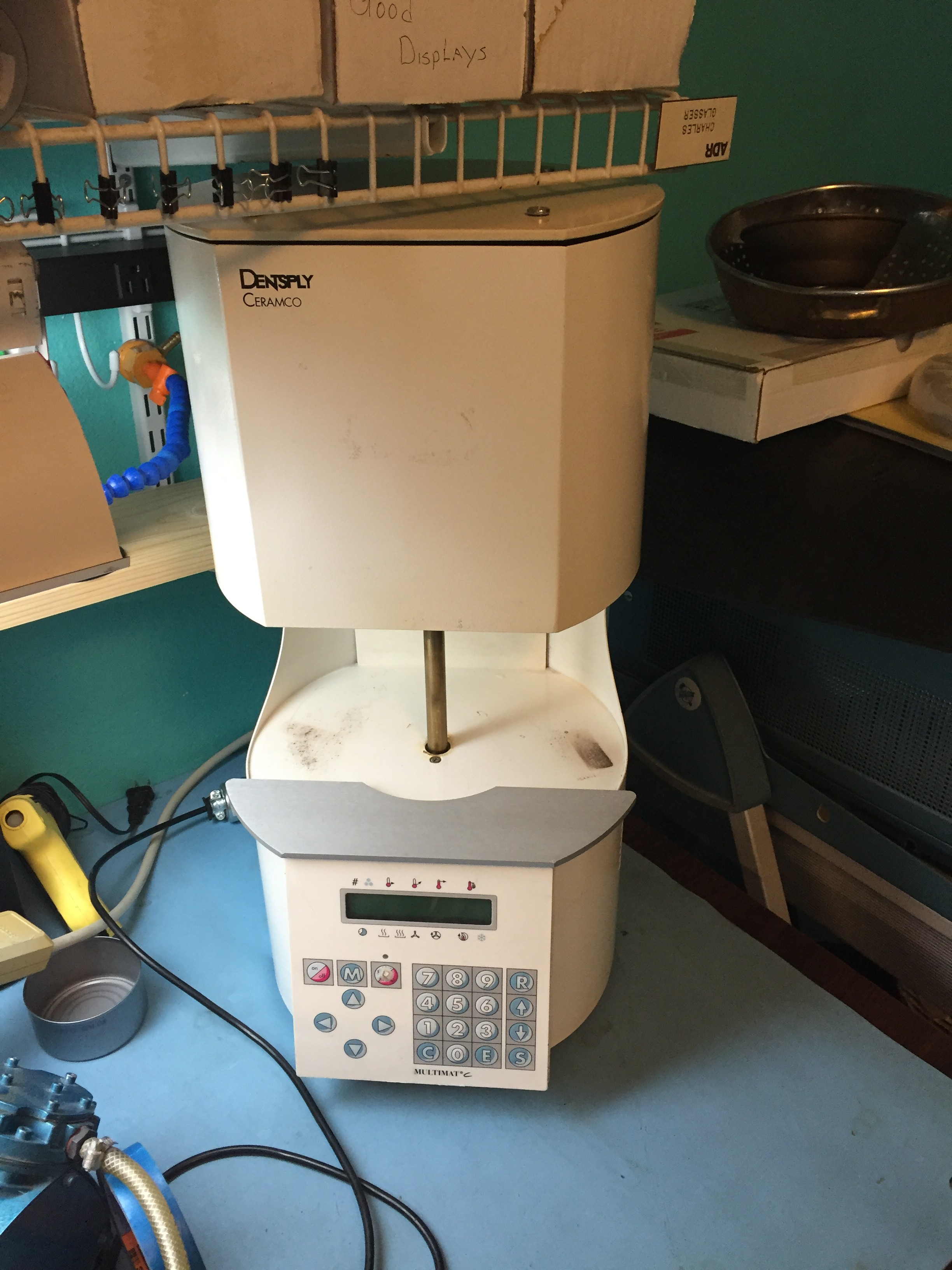
Dental furnaces are perfect for firing. I paid about $250 for this one. The electronics is very "wonky". It is going to need some work.
This is the dental furnace I'm using now. Ripped out all the controller guts and replaced it with an Adafruit Toaster Controller that unfortunately is no longer available.

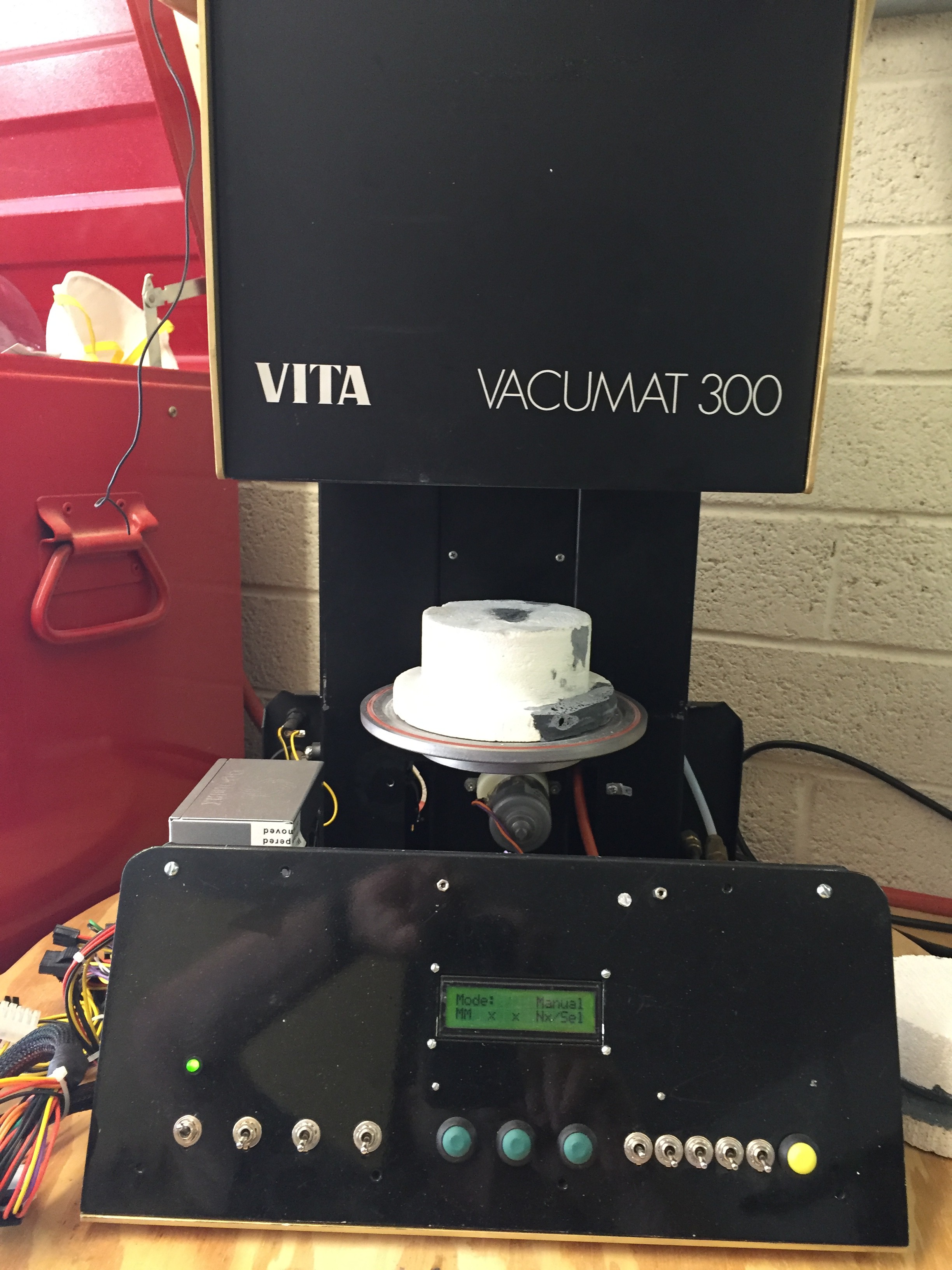
If there is a lot of material to fire then this comes in handy.
So that's it for the "Big Machines". As you may have noted everything is one huge Hack. If you should decide to build something like this keep in mind that cost goes as the cube of size! Try the trailer hitch. It will save your back.
---------------------------------------------------------------------------------------------------------------------------------------------------------------
Project 2, A Scalable MicroFluidic Signal Processor ( SMFSP) uses (1) to build a device.
Project 3, uses (2) for moving and detecting DNA demonstrating an application of the ( SMFSP) in Molecular Biology.
Project 4 will describe the multifunction CNC system used to print and fab the LTCC devices.
In project 5 I'll take the ( SMFSP) and demonstrate its use in a very advanced Brain Machine Interface that presently defines the state of the art.