 Chuck Glasser
Yesterday I met the big Kahuna, in Hawaiian a "wise man or shaman", in LTCC. Twenty minutes down the road. Who would have ever thought? The gods of electrons must be watching after me.
In summary, this project scrapes against the very fabric of technologies that have existed for thousands of years!
For ceramics, history goes back to a fertility totem the Venus of Dolni Vestonice estimated to be 26,000 years old. For laying down the inks upon the ceramic material we go to the Song Dynasty (960 - 1279 AD). These industrial process, that of ceramics and screen printing as they apply to LTCC benefit from tens of thousands of lifetimes of collective effort.
Let's take a seemingly simple example. As is known, if there is more than one layer of circuitry on the substrate the connectivity between layers is accomplished by vias. Tiny, small holes that are generally punched and then filled with a conductive ink. Experience demonstrates that to be successful, the thermal expansion of the ink MUST match that of the substrate. If it is less, the via will separate from the hole wall, and if the thermal expansion of the via is greater it will crack the substrate. The ceramic tape manufactures provide a set of inks for both the vias and the circuit traces. We can be assured that the inks in question are formulated for screen printing and NOT an Ink Jet.
In the case of producing via holes the preferred method is to use a punch and not a laser. This is because a laser may partially sinter the ceramic substrate producing stress risers and the expectation of a substrate failure at some undetermined time in the future. The 3D Fab machine can be fitted with a punch. The use of a laser operating at a wavelength that does not fuse the ceramic metal oxides, primarily Al and Si, but dissociates the organic binders, may be another option. In any case, the system will be fitted with both a punch and a 445nm Blue laser in addition to the systems already existing CO2 laser operating at 10,400 nm.
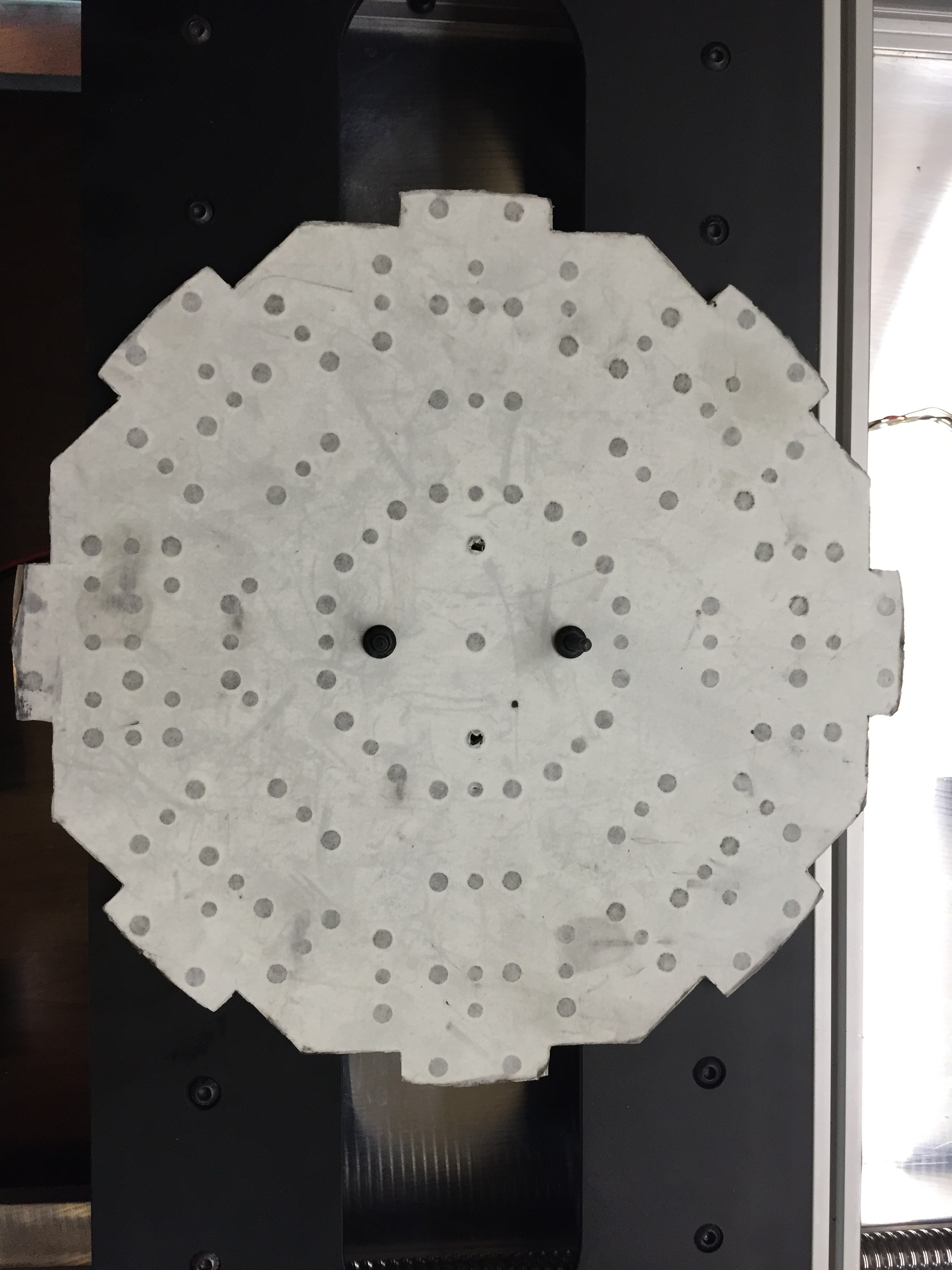
This is what you get for 36 minutes of Flow Jet water cutting. 151 precision holes. I have no idea how long this would take using conventional machining tools. I know it would take me days. And to do it without any errors. Impossible! The white paper is protecting a very smooth MIC 6 tooling plate. I'm happy to pay the $75 of water jet machine charges it cost to make.
The long bed supports up to 8 tools at any one time. In the 12 o'clock position is a conventional FDM printer head, at 1:30 a piece of 80/20 channel, at 3 o'clock a peristaltic pump that will be part of the ink printing system, and at 9 o'clock a spindle 400 Watt motor. The spindle motor has it's own mounting holes, all the other devices will mount to the 80/20 T slotted channel. There are many hours of machining left to go! So far the list of devices to hang on this fixture are, spindle motor, FDM head, ink head, camera, 445 nm blue laser, vacuum pickup, punch. At each of the positions there is a mount for a precision guide that locks the carousel in position preventing the assembly from rotating as there is about 3 degrees of backlash in the rotary mechanism.
This week the furnace was calibrated. Unfortunately, it has some software issues that need to be ground out.
Discussions
Become a Hackaday.io Member
Create an account to leave a comment. Already have an account? Log In.