 zapwizard
My goal isn't to design a 3D printed case for a phone. Instead I want to create the Pip-Boy as if it were really made by Vault-Tec.
To that end, a game-accurate 3D model has been made from a variety of sources. A painstaking amount of engineering is put into optimizing the design for cost and efficiency, while trying to keep quality high.
The design will be printed using SLS Polyamide 3D printing. This was selected not only for increased accuracy, but is required to generate all the various internal features which hold the electronics in place.
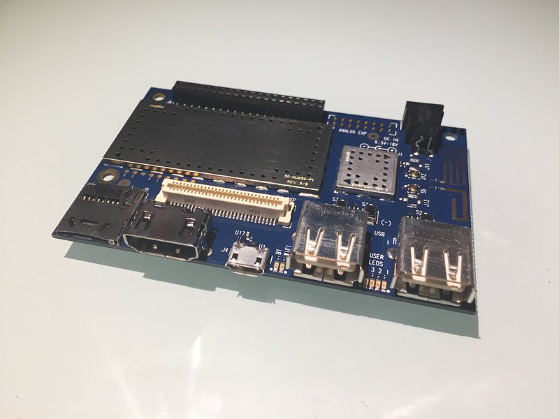
The unit will assemble using real metal pins, and screws. A custom circuit board will interface the LCD screen to the DragonBoard 410c, as well as hold the other various custom circuits.
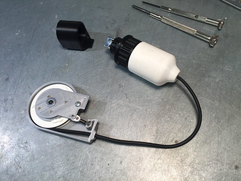
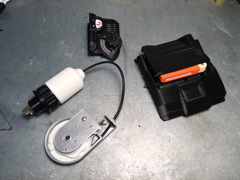
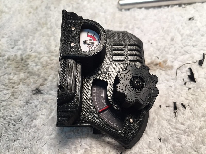
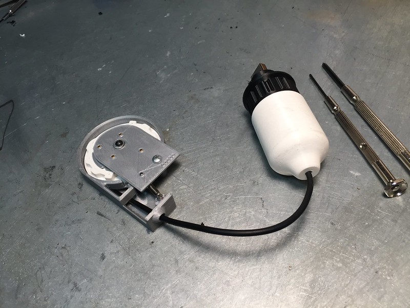
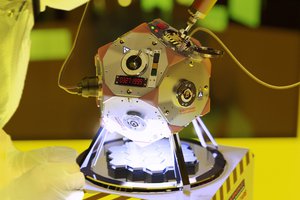
The Radiation Meter will be driven using a real gauge motor. A PIN diode gamma ray detector will be used to detect local radiation. (The meter can be driven from other source as well)
The FM radio can be tuned using the on-board knob. The control knob is geared down to a 3:1 ratio to simulate the old-school feel of a larger radio. The audio from the FM radio can be heard on the on-board speaker.
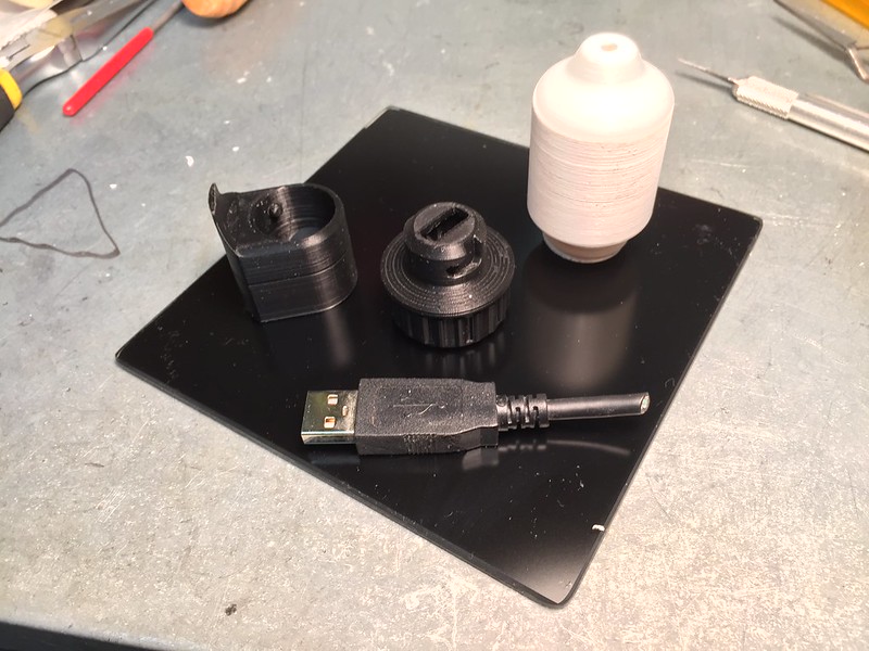
The holotape cassette deck is spring loaded with a push-to eject button. The holotapes themselves actually transmit optical data to the Pip-Boy. Using the same technology as a IR TV remote, the tape transmits a unique ID number to the operating system, which in-turn triggers an audio file or application.
A retractable USB cable is located at the back of the unit. The user can pull the cable out, which will lock in position. A tug activates the spring mechanism which retracts the cable back into the Pip-Boy.
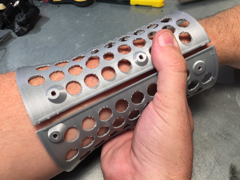
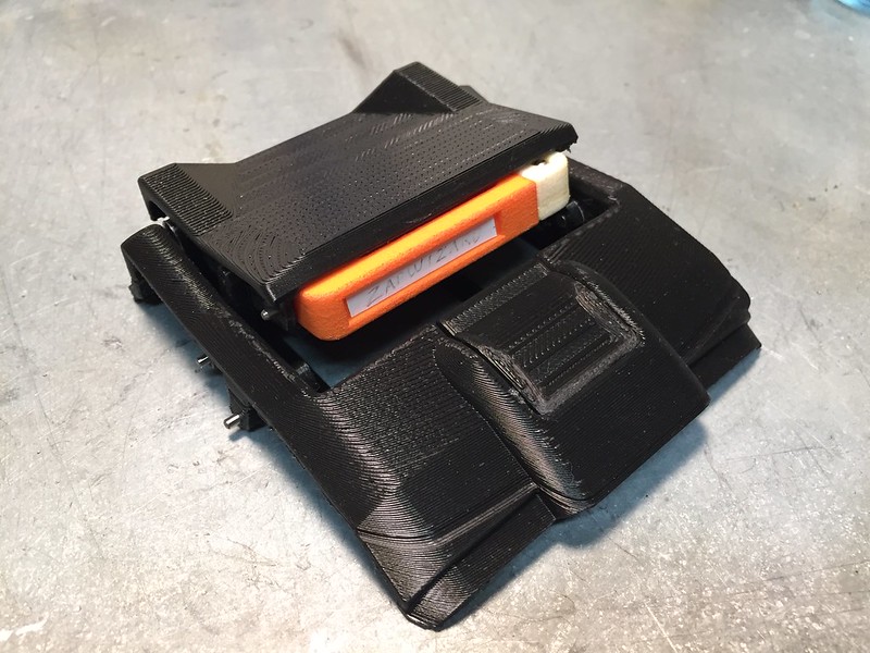


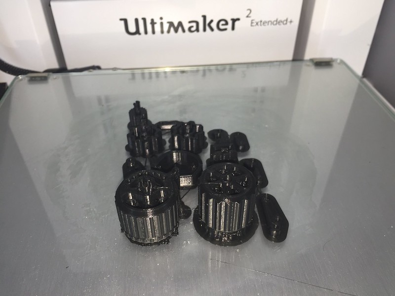 I also 3D printed my first set of prototype parts. These were printed at 0.1mm layer height with a 0.4mm nozzle on a Ultimaker 2. It took over three hours to print the parts. My goal here is to get a feel for the parts before I order them in SLS Nylon. My first impression...these parts are smaller than I expected
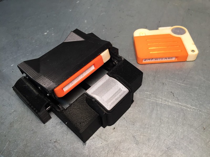
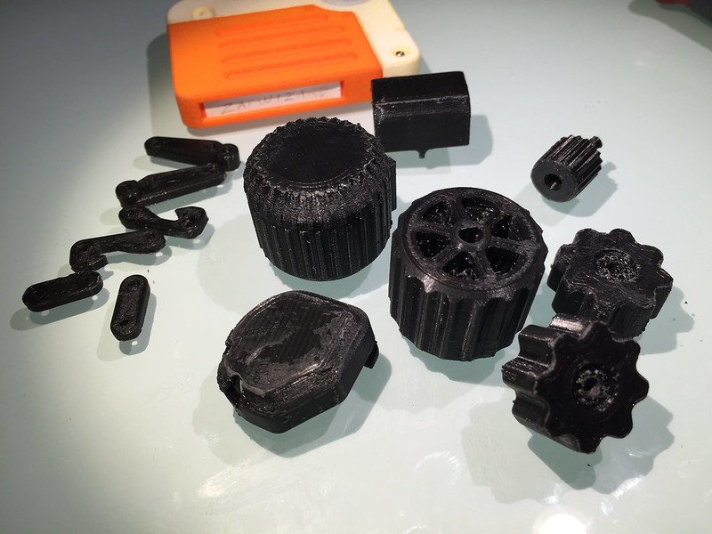 I cleaned up the 3D prints. For the most parts these are accurate enough to determine if I need to make any changes to the CAD model. As you can see even at 0.1mm resolution, the parts just don't compare to the smooth finish of the SLS printed Holotape above.
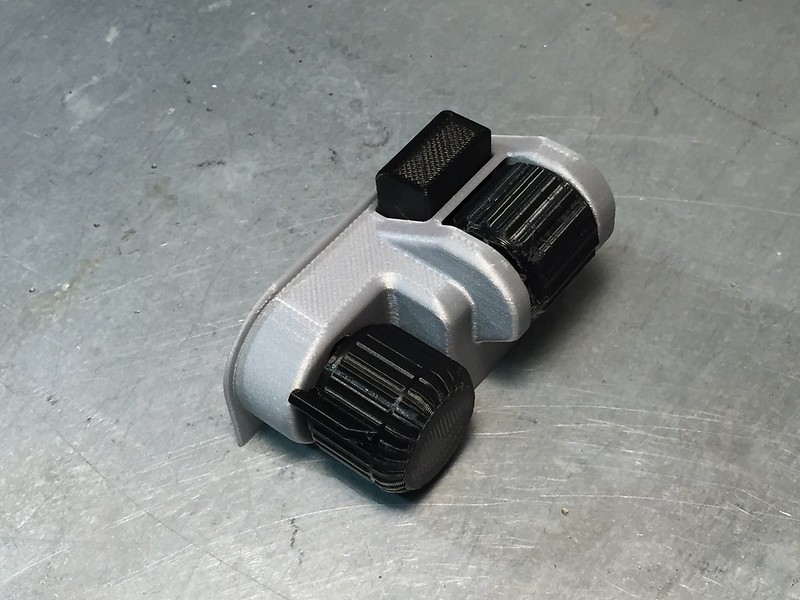
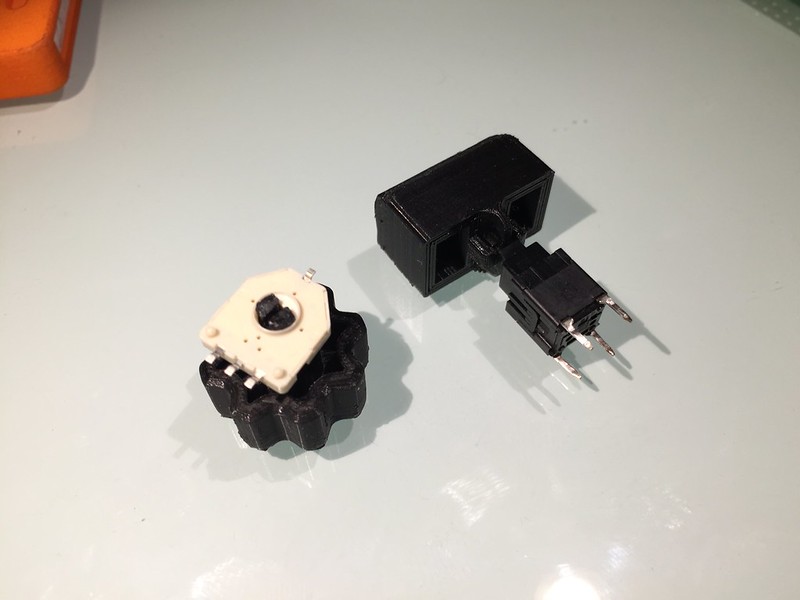 First I attached the button cap to the switch. It fits perfectly. The PLA plastic did crack, as it is fairly brittle, but it did work.
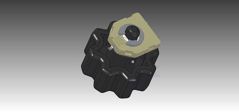 My solution is to beef up the shaft all the way to the body of the pot. Then the smaller D-shaped portion passes through the shaft. Finally a C-Clamp will hold the shaft in place behind the pot. This way the assembly can also be tested without worrying about a snap-fit failing after a few uses.
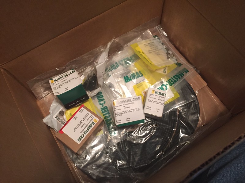
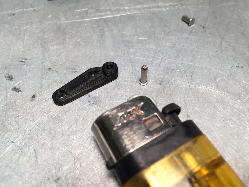 Now onto some of those new McMaster parts. And no that isn't a novelty sized lighter, sneeze and these parts go flying.
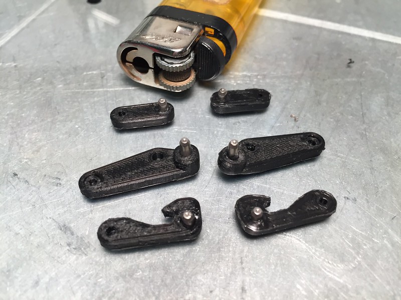 The pin will melt the plastic enough to pass through. As you can see above, a few parts got a bit too hot. But they will still serve their function well enough. Once cooled the pin is a tight fit, but can pull out. Some superglue can be used will set it forever.


 Ari
Ari
 timonsku
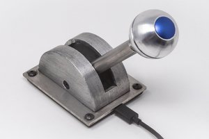
 Dewet
Dewet
how would one go about doing this to a thinkgeek bluetooth pip-boy?