 Matikas
-
1Step 1
Let's start with PCB.
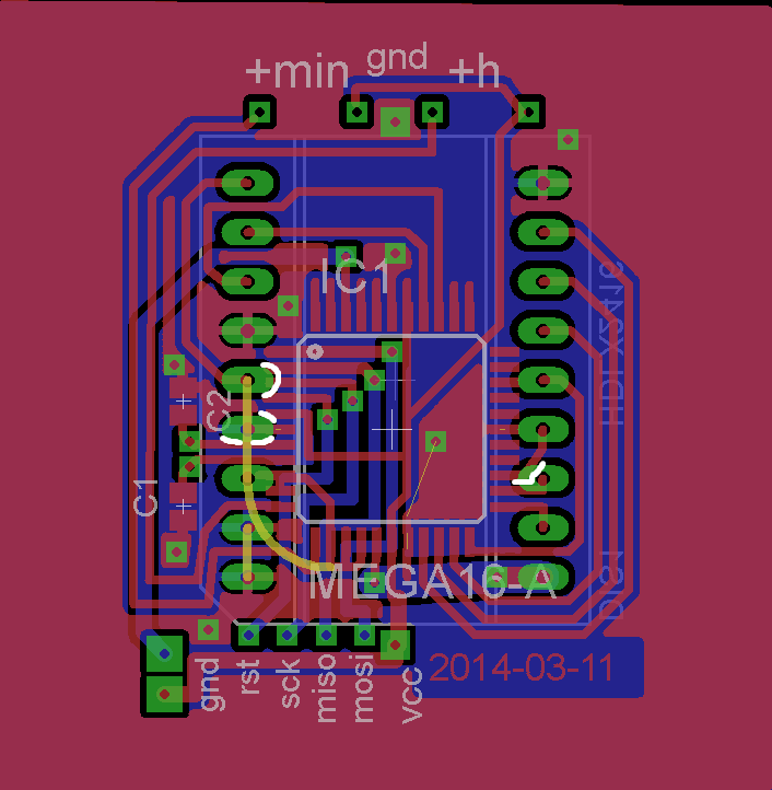
I wanted to mound display on one side of the PCB and the uc - on the other. Unfortunatelly, uc barely fits in the middle of the display's back and some pinout traces of display and uc touches where they mustn't. The traces which should not touch are marked by white color. I made the PCB on my own using fotolitography technique, so when I printed the mask for PCB, I carefully scratched the ink from those white places.
On the upper side of the PCB there are contacts for buttons to set minutes and hours. Below there are contacts to attach a programmer. On the lower left side those 2 bigger contacts are set for ATmega16 INT2 pin. I thought I'd use it to turn on the display, but later I changed my mind so I left it unconnected. Holes between C1 and C2 are for 32.768 kHz crystal. Those yellow traces should be connected by using wire.
By the way, one more thing: if you check closely, you will see that display is not connected to VCC - it's power pins are connected to ATmega's PD0,1,4,5,6 pins. When testing the display, I've noticed that when it is blanked it still drains about 1mA of current at 5V. I wanted to cut off the power totally so I decided to power it from ATmega16 pins directly. According to mega's datasheet it can source up to 40mA per pin and 200mA per port, so 5 pins of PORTD makes the max ammount. The HPDL drains 150 mA max so it is enough. When I want to turn off the display I write logical 0 to mentioned earlier PORTD pins and to PD7 which is connected to display's blank pin.
![]()
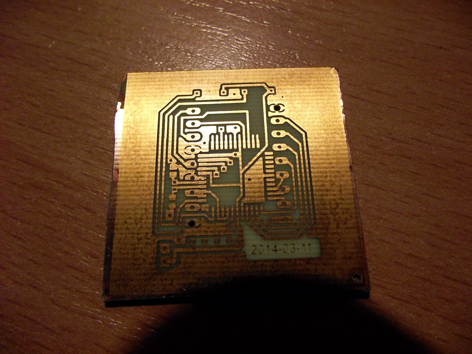
The PCB (check the "scratched" traces):
![]() All components soldered:
All components soldered:![]()
-
2Step 2
The code is next.
It's available at my github, I'll just explain a little bit. The timer2 is set to overflow and it's prescaled to 1024. With 32768 Hz clock it overflows every 8 seconds. Then I add 8 secs to the time variable. I've also set INT0 and INT1 interrupts for setting hours and minutes. When you press any of these when display is blank - it will only turn it on by powering and unblanking it. Then you have to wait 2 s till you can set the time. The display goes off after 16s when any button was pressed. Moreover the power-down sleep mode is used to reduce power consumptions of the uc.
-
3Step 3
Add a battery holder and upload the firmware.
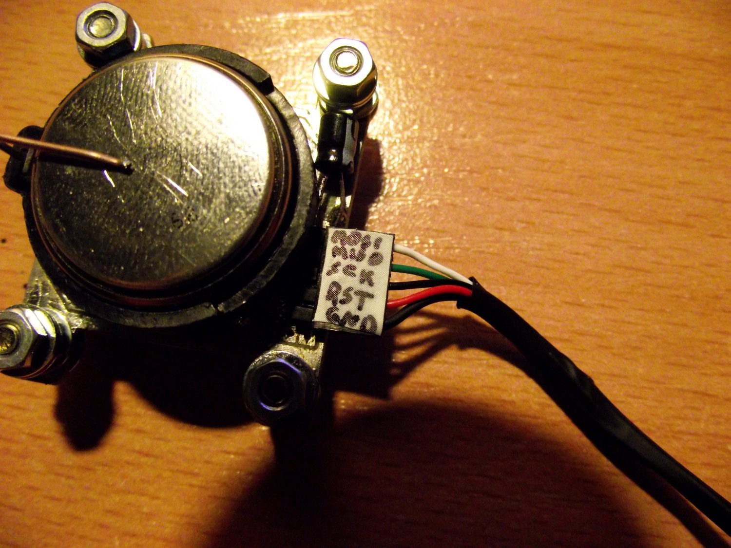
I had a holder which was designed for thinner battery than CR2450. I wanted to bend it's top pin but I broke it, so I had to make it from wire. By the way, I had to extend the gap between it's pins which need to be soldered to PCB - I've cut one and soldered a extending wire. BTW, in the foto you can see that I put the battery upside-down. I designed it like this on purpose, because battery in this way holds better in this holder :) .
In the foto you can see the programmer attatched with it's pinout.
![]()
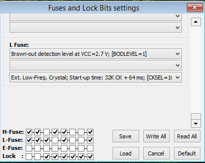
Don't forget to set the right fuses (I use khazama AVR Programmer to flash AVR):
![]() The most important thing is to set correct clock fuse for 32,768 crystal and to disable JTAG. When it's enabled - you can not fully manipulate PORTC pins. I had the problem before I noticed it that HPDL was showing some random characters instead of numbers - this was because data pins are PORTC pins.
The most important thing is to set correct clock fuse for 32,768 crystal and to disable JTAG. When it's enabled - you can not fully manipulate PORTC pins. I had the problem before I noticed it that HPDL was showing some random characters instead of numbers - this was because data pins are PORTC pins. -
4Step 4
Make a whristlet:
It is very easy. You can see holes on my manufactured PCB. I just mounted screws through them and bent 2 pieces of wire like in the foto which can be placed on those screws over cut off gaps of PCB.
![]() The whristband itself is made of flat cable. I've soldere one it's end to one of those bent pieces of wire:
The whristband itself is made of flat cable. I've soldere one it's end to one of those bent pieces of wire:![]() Then I bent the other end of the cable that I could fasten it to the other bent piece of wire. And that's it. Just don't make it too tight because after some time your whrist will hurt :) .
Then I bent the other end of the cable that I could fasten it to the other bent piece of wire. And that's it. Just don't make it too tight because after some time your whrist will hurt :) .![]()
HPDL watch
A watch with an old-school HPDL-2416 display. It is driven by ATmega16.
 All components soldered:
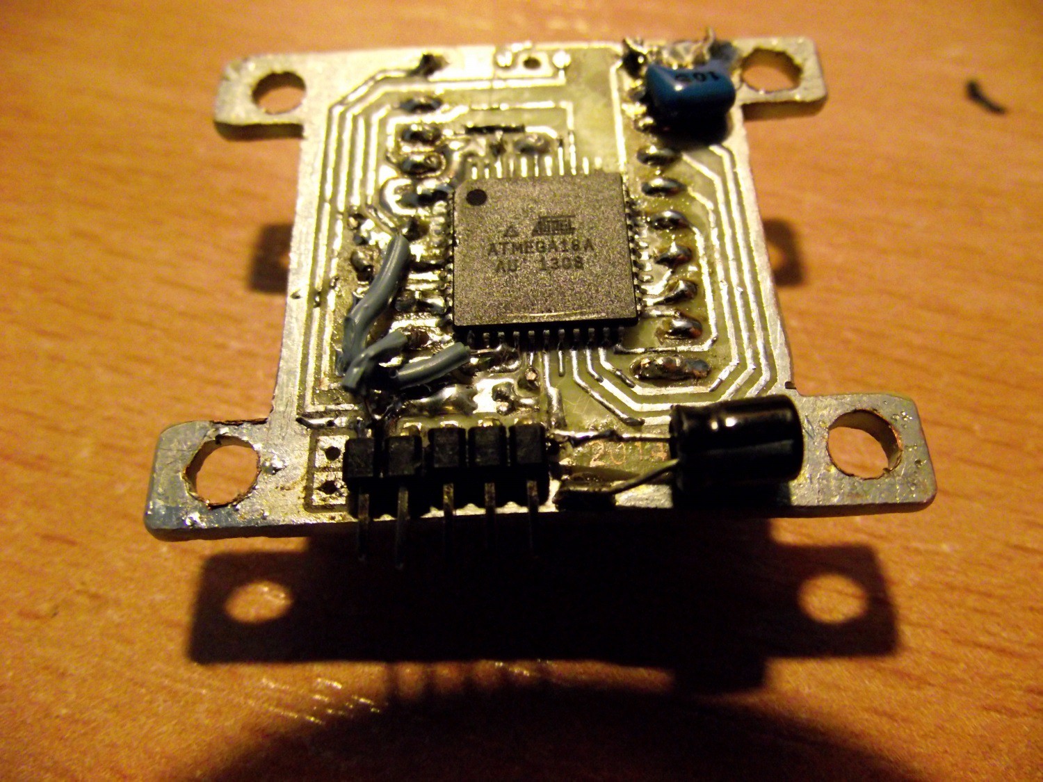
 The most important thing is to set correct clock fuse for 32,768 crystal and to disable JTAG. When it's enabled - you can not fully manipulate PORTC pins. I had the problem before I noticed it that HPDL was showing some random characters instead of numbers - this was because data pins are PORTC pins.
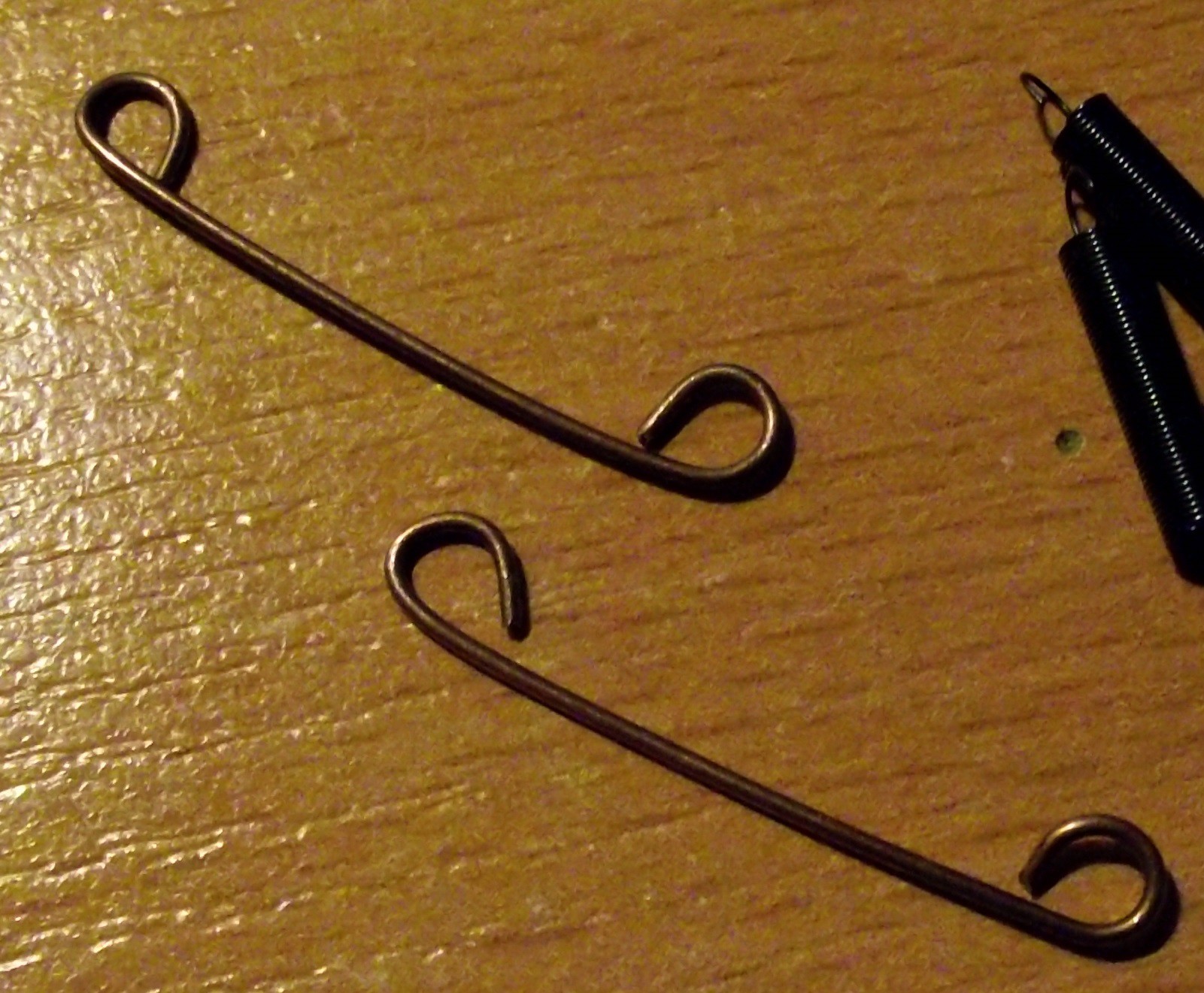 The whristband itself is made of flat cable. I've soldere one it's end to one of those bent pieces of wire:
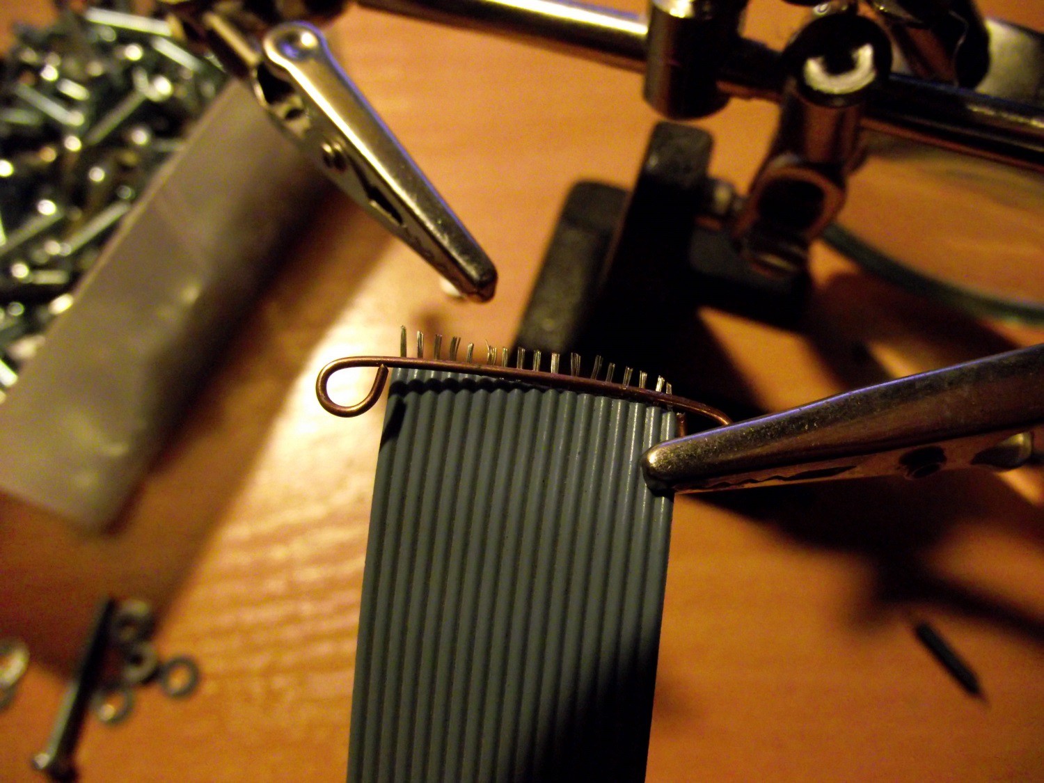 Then I bent the other end of the cable that I could fasten it to the other bent piece of wire. And that's it. Just don't make it too tight because after some time your whrist will hurt :) .
Discussions
Become a Hackaday.io Member
Create an account to leave a comment. Already have an account? Log In.
Nyce Project I will let make dis project but I will use HPDL1414 :D
Are you sure? yes | no
Are you sure? yes | no
Are you sure? yes | no