Close
0%
0%

MO5 interface boards

I'm a Thomson MO5 fanatic and despite its bad rep, it's a very nice machine that is easy to extend.

Similar projects worth following
I have learned to program on the MO5 in France in the mid 80s. It was a widespread platform aimed at education, running on a 1MHz 6809E with ROM BASIC, 48K of DRAM, 320×200px color display and... 2 extension ports !
* One is a cartridge port that replaces the BASIC ROM to provide immediate load of programs (more expensive than cassette and not writable but immediate boot). There is also a 64K RAM extension cartridge (see the logs).
* One is a more complete bus extension where you access more useful signals, so you can create your own GPIO boards. Indeed, all I/Os are plugged there.

I'll try to build circuits for both interfaces and for various applications, eventually targeting the TO8D (its big brother with more RAM, better video and integrated diskette drive). I'll also try to 3D-print cartridge enclosures !

I'm not reinventing the wheel (too much) here. There have been articles about plugging interfaces to the MO5 since, well.... it existed. The French magazine Science & Vie used to have a few pages each month around 1986 where a simple circuit was made and some BASIC listing was provided to make it work. This was my first exposure to actual computer hacking and I was not even 10. During the following years, I turned to these articles to try and learn how to make it do more than what it was meant to do... and failed because of lack of  support, time, money, experience, tools, parts availability... Oh and I didn't even have a computer. Soon, I would get an Amstrad/Sinclair PC200 (8086@8MHz) and my conversion to the ugly PC world would start.

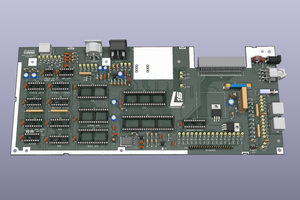
The MO5 is a very hackable machine, and despite its shortcomings, it's easily repaired (except the keyboard, damnit). I had a book detailing its internal design since my teens so I know well how it works, what it can do and what it can't.

Manuel Technique du MO5 (djvu)

I love it even more now because the Raspberry Pi has become a complicated system that changes every year and requires a lot of precautions... Linux has slowly become a huge beast... Power comes at a cost !

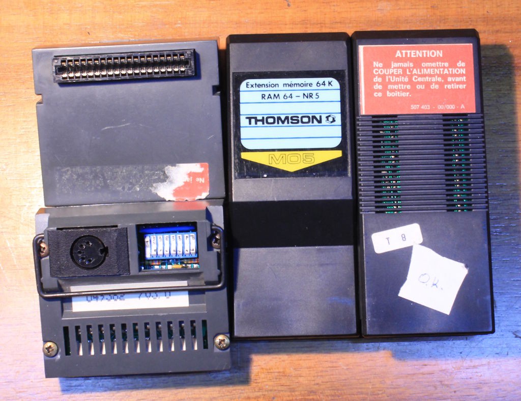
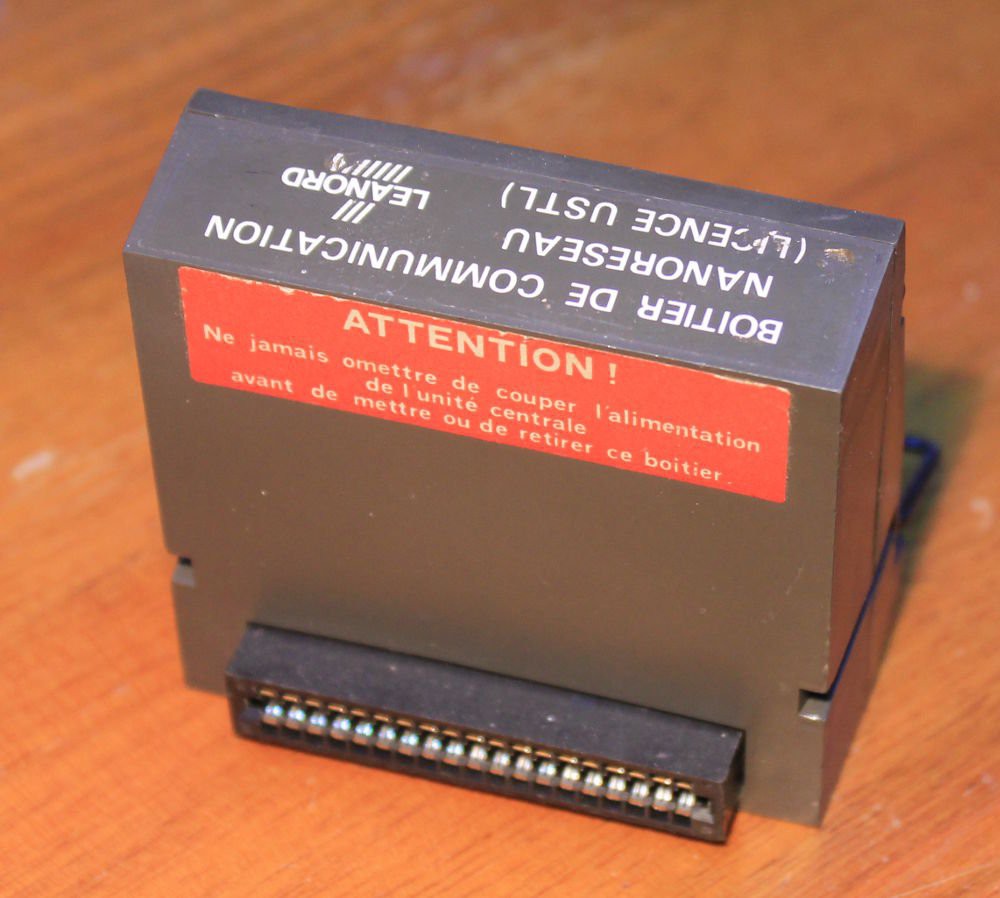
The Thomson MO/TO family of computers is still actively used by many French enthusiasts, 30 years after Thomson's home computer branch folded (a brief history is available in French). A great quantity of information is available at http://dcmoto.free.fr/ including software, books and technical documents. It's also a recurring theme on forums such as https://forum.system-cfg.com/


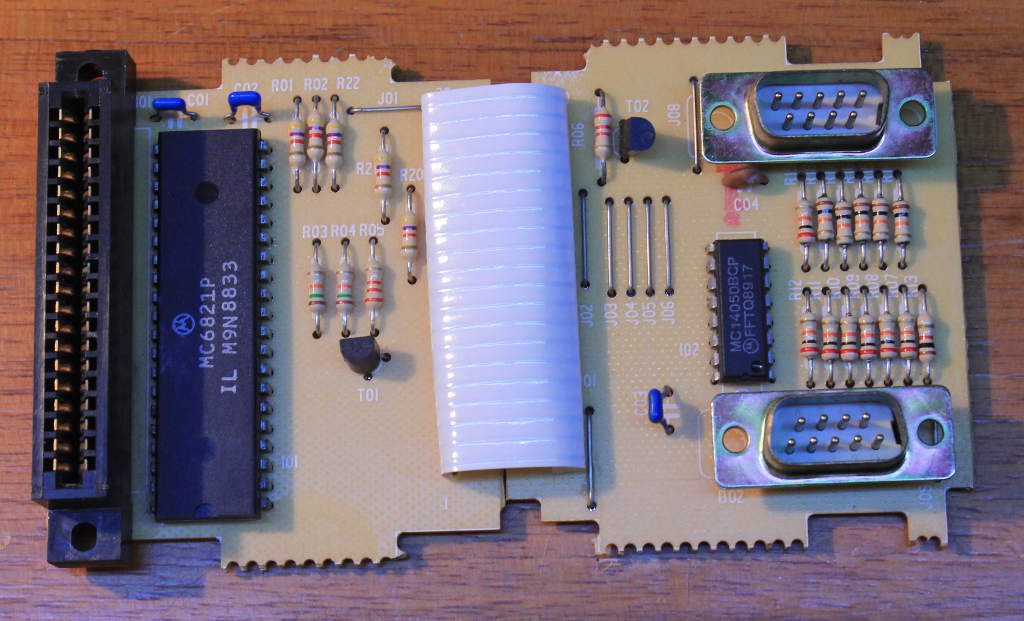
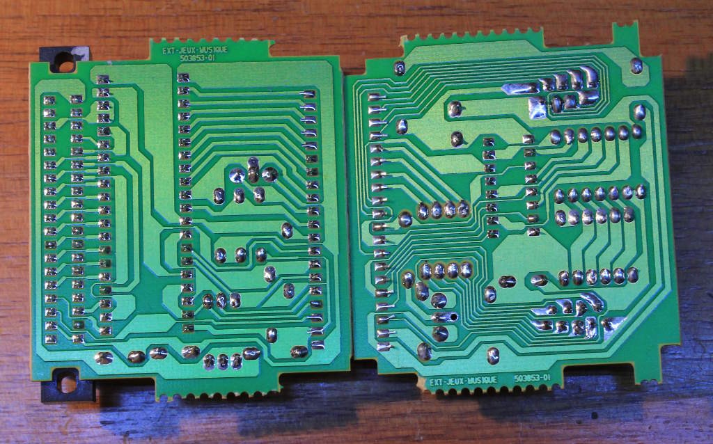
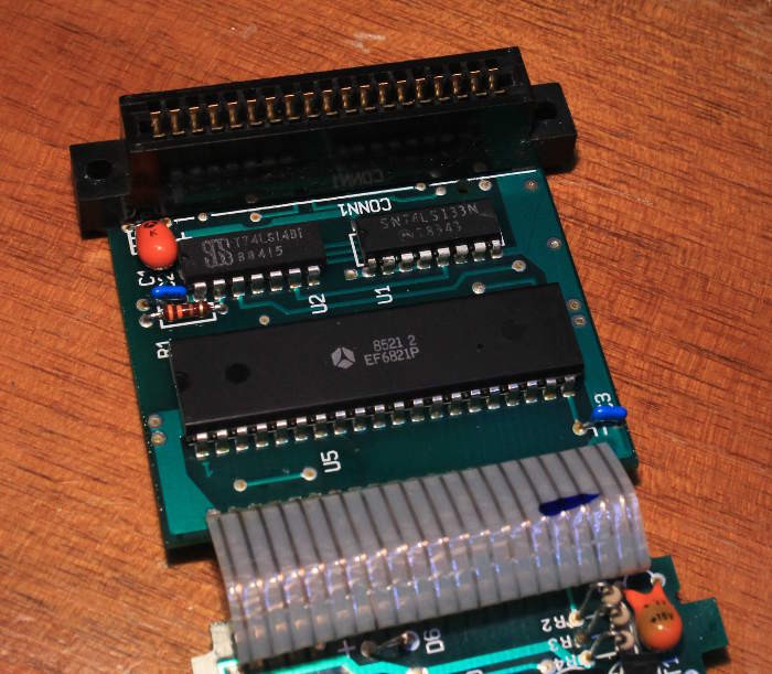
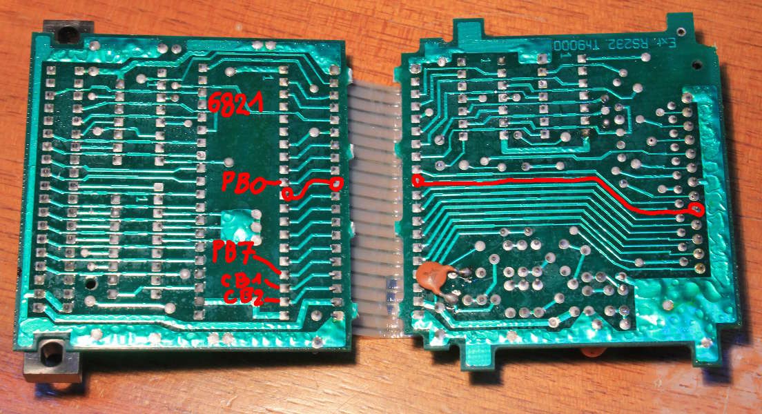
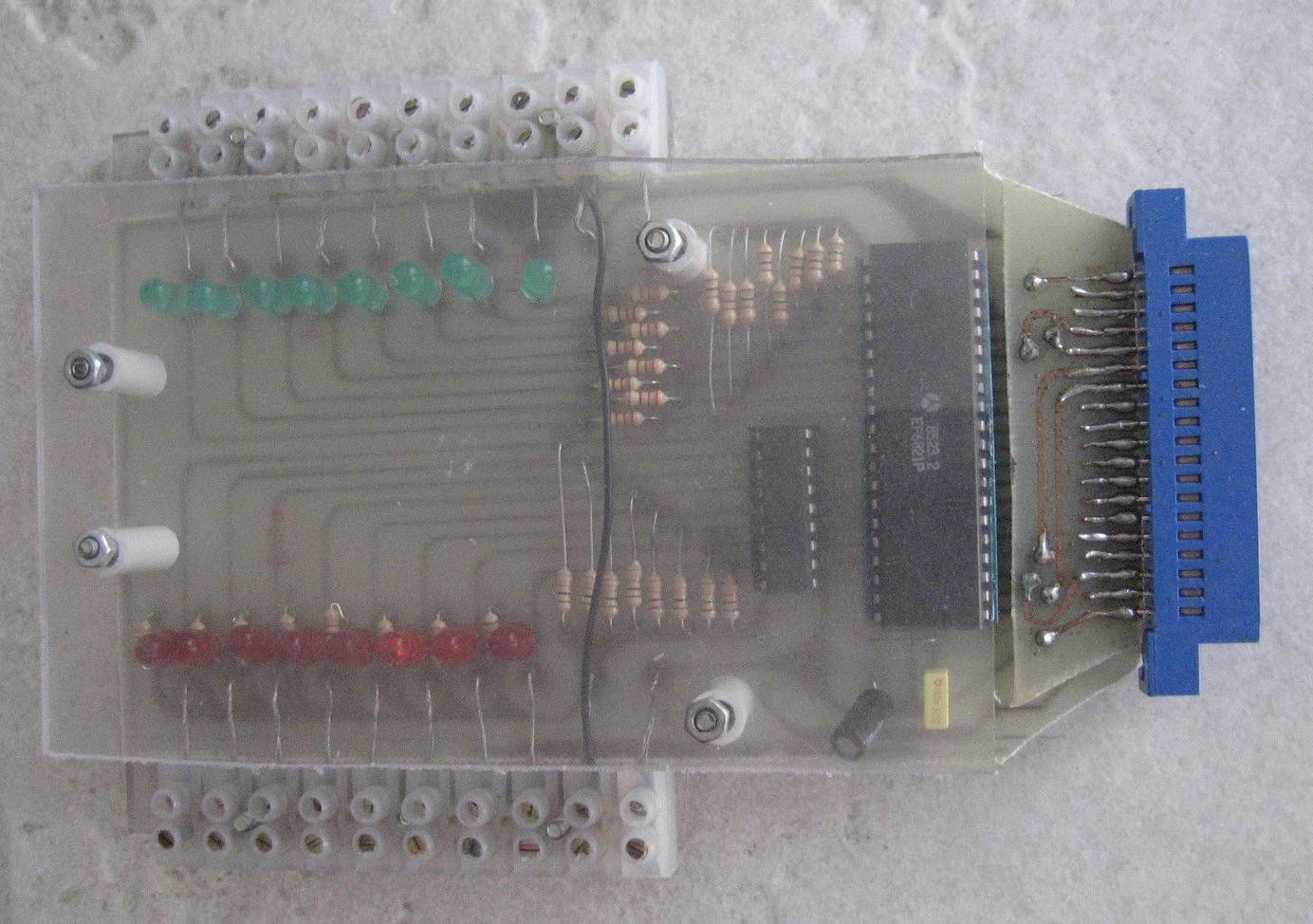
For now I just want to make basic hardware interfaces : the boards that connect to the cartridge slot and the bus extension port. There are a few challenges but nothing crazy, it's plain old tech :-)

Later projects include :

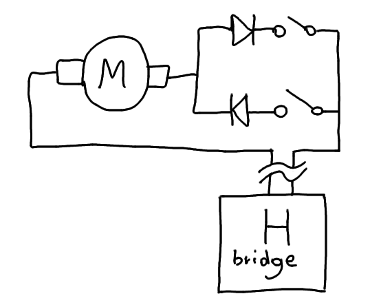
  • GPIO interface board (optoisolated ?) to control sensors, motors, coils, automation... for example to control a model railroad circuit :-)
  • Dual-port SRAM cartridge with external upload/download => enable development of cartridges in assembly, or a multicart system ?

But for now I just want to make simple circuits and boards, and document them here, even offer some Gerber.


Logs:

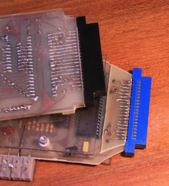
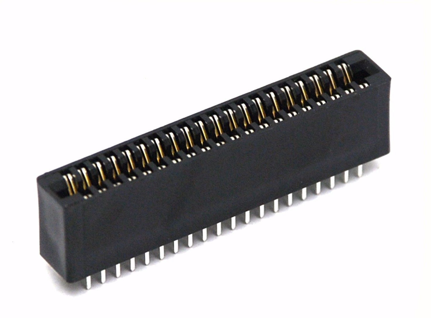
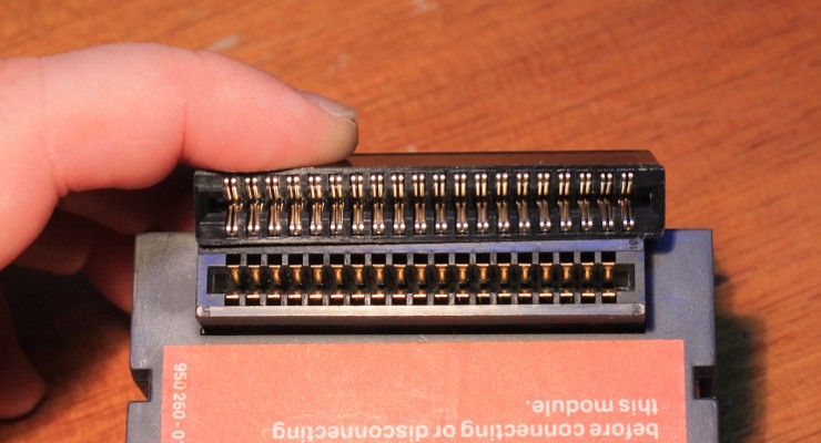
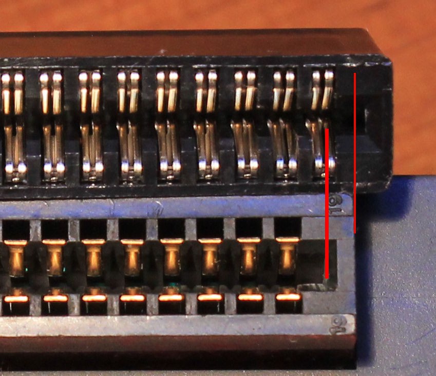
1. Damned connectors
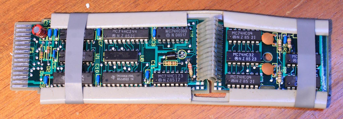
2. Extension surprises
3. More extensions
4. Servomotors...
5. Edge connectors (again)
6. Change of strategy 
.

  • Change of strategy

    Yann Guidon / YGDES05/05/2018 at 20:57 0 comments

    To control the switches, I have found LEGO motors so the RC servos are now out of the project.

    In HO trains, and smaller, the switch was (is?) actuated by a solenoid. I have also seen a switch actuated by a DC motor and a rack, supplemented with 2 limit switches. That makes "a certain number" of wires and IO signals... The computer has to wait for the proper limit switch to be active before turning the current off, and missing the information could damage the mechanism.

    The switches could also be in series with the DC motor to prevent damage. But then, once the position is reached, it's impossible to power the motor to go in the reverse direction. And I don't wan't to use 3 wires (one per direction).

    So in my old habit of reinventing the wheel, I came up with the following circuit that is fail-safe, thanks to diodes in series with the appropriate limit switch.

    The end of actuation can be detected by a current sensor on the supply rail of the H bridge.

    The computer needs 2 output signals (to control the H bridge) and one feedback input from the current sense. A single 74HCT273 can control 4 switches. The current sense could even be shared among all the H bridges so the input signal is only 1 bit. A standard H bridge IC provides all these features, though the L293D lacks the current sense feature. OTOH the L298 is overkill for the task. And limit detection might not be absolutely required after all (it could be used for failsafe/fault detection).

    Now, the H-bridge must also be "safe" with some logic to prevent simultaneous conduction of both branches of the bridge, but there is nothing left to invent there :-) Some AND gates and inverters do the trick.

  • Edge connectors (again)

    Yann Guidon / YGDES04/13/2018 at 00:46 0 comments

    In parallel with trying to source original extension modules, I decided to finally buy the DIY modules I saw on eBay. And they have arrived.

    It's obviously old work, made by a semi-competent hobbyist (it's not awesome but it works). The traces are ugly and soldering job is lousy but there is a hope to at least recover one of these 38-pins connectors, as well as a couple of the socketed 6821 (made by Thomson under licence in 1985).

    I'm sad to throw away most of the board, just for one connector, but...

  • Servomotors...

    Yann Guidon / YGDES04/10/2018 at 01:24 0 comments

    Something strikes me now and it sounds almost ridiculous but as always, it's a matter of context.

    One of the applications of this project is to control a model/miniature railroad circuit. Sensors are classic (contact, ILS, optical...) but actuators need more consideration. The most important part is to move the switches, it must be electromechanical. HO trains can do it with an electromagnet but mine don't have enough force so a RC servo is the way to go.

    So now the challenge is to send the right pulses to the right circuit. Moreover the servos have significant idle power requirements and they tend to oscillate around the requested position so their power supply must be turned on only when a change is requested.

    Fortunately, I expect that only one switch moves at a time and the control circuit is significantly simplified.

    A 74CHT138 selects the power supply to turn on : the negative-active signal can drive a P-MOSFET to power one servo out of 8 (or 16).

    A 74HCT238 can then send a sw-controlled pulse to this servo. A simple loop in BASIC will be enough...

    16 individual outputs require 4 bits of address. The power and pulse signals require 2 more bits. Let's say that address 0 is a null/void address, so 6 output bits are sufficient. This could be implemented with a 74HCT273 or a MC6821 with room to spare.

    For example, extra bits can drive a 74HC259 or two (to control lights or other signals)


    So I'm trying to do something more or less like that :

    However the LEGO implementation is expensive... I don't have such motor, and i'd need many, and I'm far from rich. However I have some cheap servos. I just need to find how to adapt the lever to the servo and I'm mostly done.

  • More extensions

    Yann Guidon / YGDES04/07/2018 at 01:03 0 comments

    How do you solve an extension problem ? Get more extensions ! I found a couple more Nanoréseau adapters on classifieds:

    It's interesting to know that the Nanoréseau required quite a lot of RAM so each adapter comes with a memory extension (64KB). I have already seen this extension in a MO5 computer as a "hack", where the cartridge port was removed to integrate the 64KB PCB inside the box. One can see the 4164 DRAM chips, 2 of them are enough to create a 64KB block.

    This is very interesting indeed.

    One important aspect of this project is to create new extensions. Now I can measure the physical dimensions (bring the caliper !) to make compatible cartriges as well.

    I already had small ROM cartridges and I can compare with them.

    (pictures here)

    I also found a "game port extension" that contains a 6821 that drives a 6-bits R/2R DAC and a couple of switch-based joysticks. Note that the board contains no address decoder, isn't it interesting ? :-)

    By cutting the middle connexion, we can get the 6821's ports and hook 16 bits (?) of bidirectional IOs, which could be enough for simple robotics and/or model train control...


    So overall, most of the MO5's extensions are easy to modify and repurpose. It's not only a great platform to learn about programming, but also to learn about hacking :-)

  • Extension surprises

    Yann Guidon / YGDES03/31/2018 at 18:08 2 comments

    As I struggled to get the right connector for the extension slot, I tried to get whole modules with the intention to unsolder the female connector.

    Let's start with the Nanoréseau controller. I don't use this type of network (based on the MC6854) so let's rip that module up.

    But wait, there is a board with strange pads. Actually it's not pads but machined female sockets for the MMI PAL (address decoder ?) and a 24-pins EPROM... So this means that I can burn my own programs and just plug a Flash (?) with almost no modification to the board ? There is even a DIP switch at the other end so I could select a region of the Flash to use, and create a multicart system...

    And I discover only now that this hack is already used by others, see at http://dcmoto.free.fr/bricolage/cs91-280/index.html


    OK so the Nanoréseau is out of the way... I also have a communication port, that looks like a Centronics over DB25 interface, just like on the PC. Let's rip it up !

    Oh wait... It's a 6821 inside and apparently, one port (8 bits ?) is directly tied to the DB25 connector ! So it could be used for a direct, rough output for prototyping.

    With CB1 available, there is one interrupt input available.

    With CB2 also available, both interrupt input and bit output are possible.

    And each of PB's bits can be configured as input or output, so it's about 10 GPIO...

    I have no idea why there is RS232 level converters because bitbanged asynch serial would be SLOW and SW-heavy. But it could be useful as high-voltage I/O...


    So these old circuits are not so lousy after all. There is a lot of potential for hacking and reuse... but this doesn't solve my initial problem, and I don't want to solder anything to the extension fingers of the main unit...

  • Damned connectors

    Yann Guidon / YGDES03/31/2018 at 01:56 0 comments

    The extension port is  a bit of PCB  that extends outside of the box and provides 19×2 signals for external boxes.

    Loooong ago, I had the matching female connector (while it was still semi-popular, early 90s). It's now impossible to find. And NO store I know (online or brick&mortar) has it anymore.
    I can still find a few rare extension boards online but they are pretty unadapted:

    (this one uses a EF6821 for GPIO but 74HCT273 would be good as well)

    Still, impossible to find original 19x2 connectors. Maybe I'll have to desolder one from existing modules ?

    I resolved myself to get standard 20×2P connectors in the hope I could "tweak" them.

    The mechanical adaptation is a bit tricky but not impossible...

    Here is an original extension module (it provides some sort of network)

    It mates on this edge connector :

    The mating is possible with special grooves on the sides, that prevent reverse or shifted connection :

    The new connector is almost identical, only one pin larger :

    Adaptation will be a bit tricky :

    The last position must be half-filled...


    Another possibility is to change the format. One adapter can plug in the computer with a vintage socket, and provide all the signals to a more modern format (like PATA 20×2 connectors ?)
    The extra pins can provide more GND and of course a key pin to prevent shift/reverse connections...

View all 6 project logs

Enjoy this project?

Share

Discussions

Similar Projects

Does this project spark your interest?

Become a member to follow this project and never miss any updates