 Yann Guidon / YGDES
To control the switches, I have found LEGO motors so the RC servos are now out of the project.
In HO trains, and smaller, the switch was (is?) actuated by a solenoid. I have also seen a switch actuated by a DC motor and a rack, supplemented with 2 limit switches. That makes "a certain number" of wires and IO signals... The computer has to wait for the proper limit switch to be active before turning the current off, and missing the information could damage the mechanism.
The switches could also be in series with the DC motor to prevent damage. But then, once the position is reached, it's impossible to power the motor to go in the reverse direction. And I don't wan't to use 3 wires (one per direction).
So in my old habit of reinventing the wheel, I came up with the following circuit that is fail-safe, thanks to diodes in series with the appropriate limit switch.
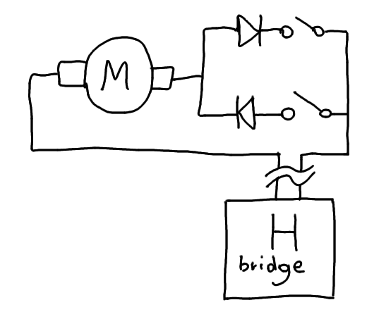
The end of actuation can be detected by a current sensor on the supply rail of the H bridge.
The computer needs 2 output signals (to control the H bridge) and one feedback input from the current sense. A single 74HCT273 can control 4 switches. The current sense could even be shared among all the H bridges so the input signal is only 1 bit. A standard H bridge IC provides all these features, though the L293D lacks the current sense feature. OTOH the L298 is overkill for the task. And limit detection might not be absolutely required after all (it could be used for failsafe/fault detection).
Now, the H-bridge must also be "safe" with some logic to prevent simultaneous conduction of both branches of the bridge, but there is nothing left to invent there :-) Some AND gates and inverters do the trick.
Discussions
Become a Hackaday.io Member
Create an account to leave a comment. Already have an account? Log In.