 David Brown
So i've finally got around to testing the new board, which appears to be behaving itself well with all of the components remaining nice and cool. The PID network is quite sensitive and will require some careful evaluation. I'm spent out so this will have to wait for a while to put together a DIP switch and range of capacitors / resistors similar to that on the evaluation board.
Soldering the main chip was done using a 5mm thick piece of aluminium plate over the gas hob and plenty of light flux over the pre-tinned pads.
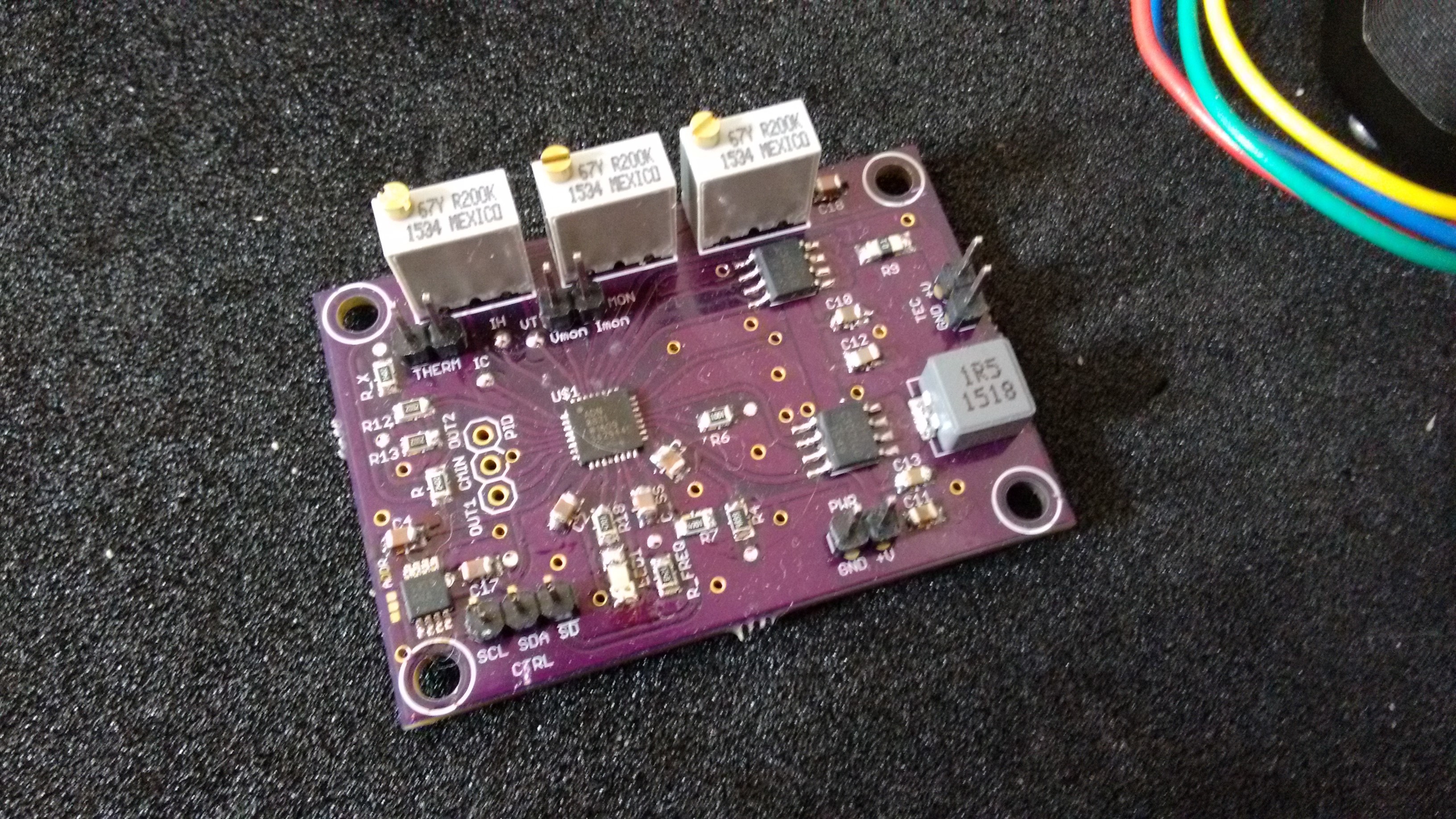
I discovered one minor error which was the value of one of the resistors should have been 50k rather than the 4.7k that I had it at. I've updated the calculations and schematic / parts list to reflect this. I may also need to replace the DAC as the output is sawtooth with variation of about 0.25v which it realy should not be doing.
[Edit. replaced the DAC and output persists, no issues with the reference input voltge which is nice and stable. Looking again at the circuit the voltage is a function of both the DAC and the feed-back in the op-amp in the controller. So I think that was a false alarm on my part. Further playing shows that the PID elements are very sensetive and really do need optimizing on the actual hardware.]
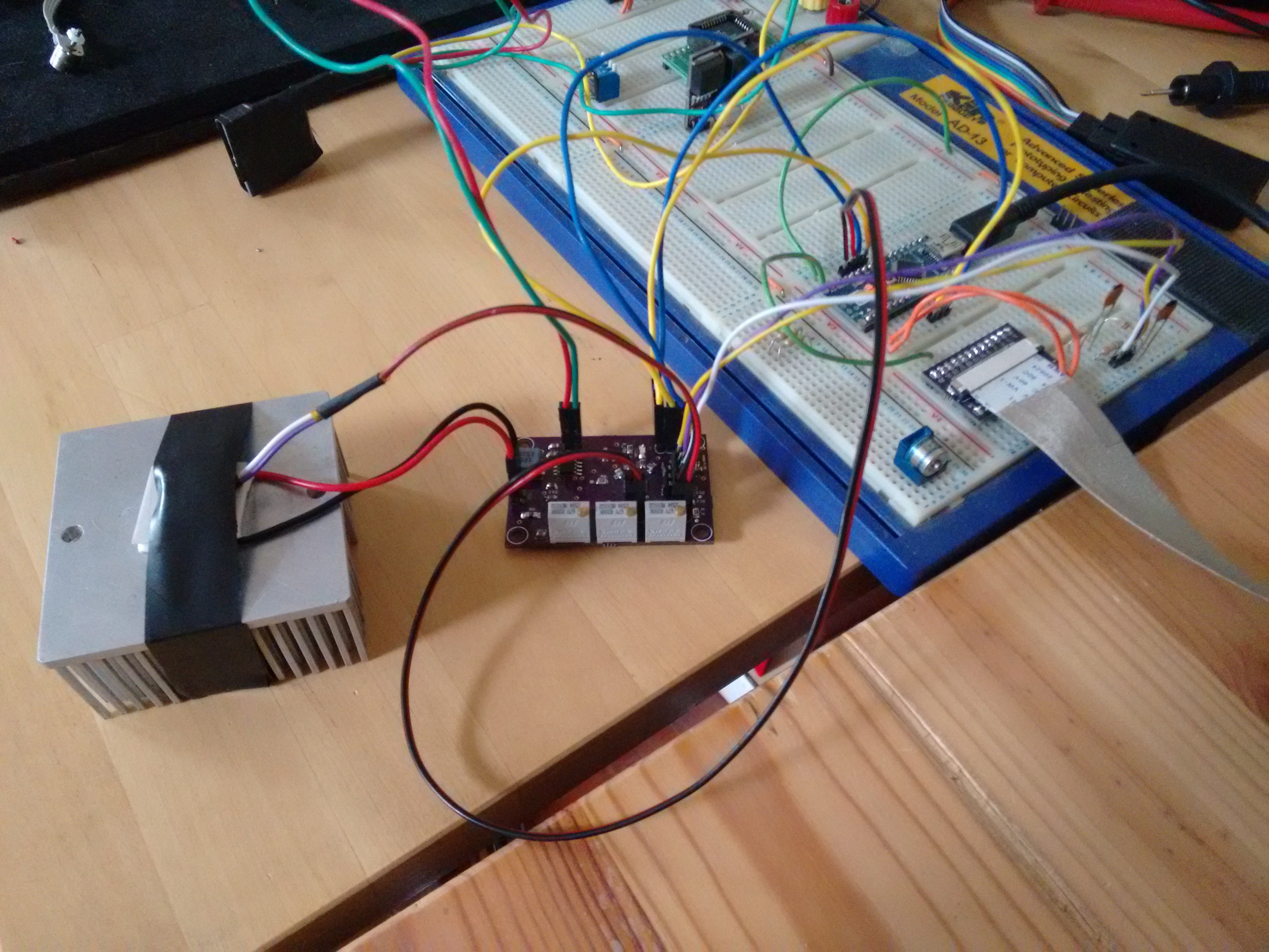
Test setup; TEC, thermistor and heat sink plus connections to Arduino for control and monitoring of current and voltage signals
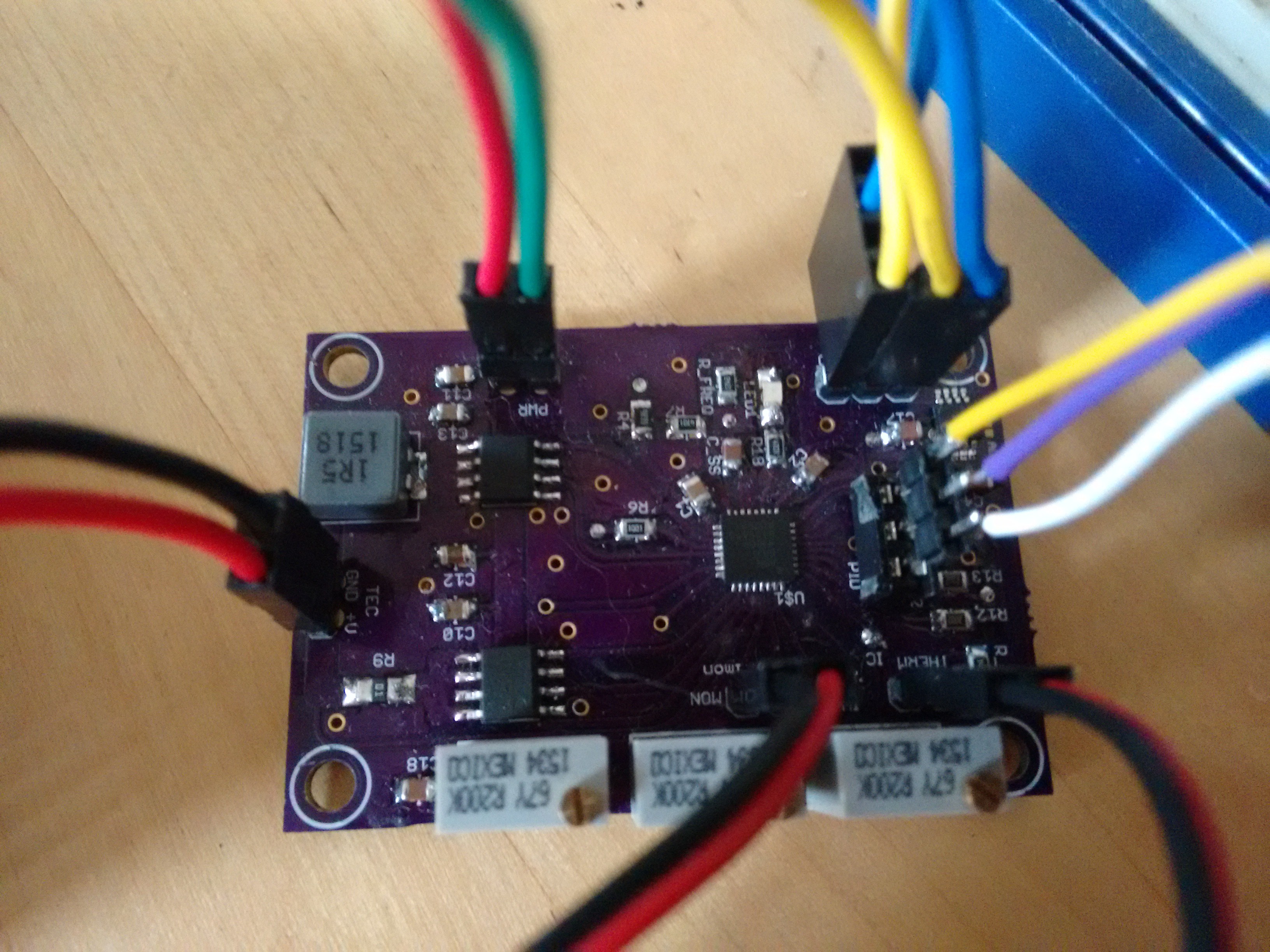 View showing yellow, purple and white wires from the socket that allow remote prototyping of the PID elements
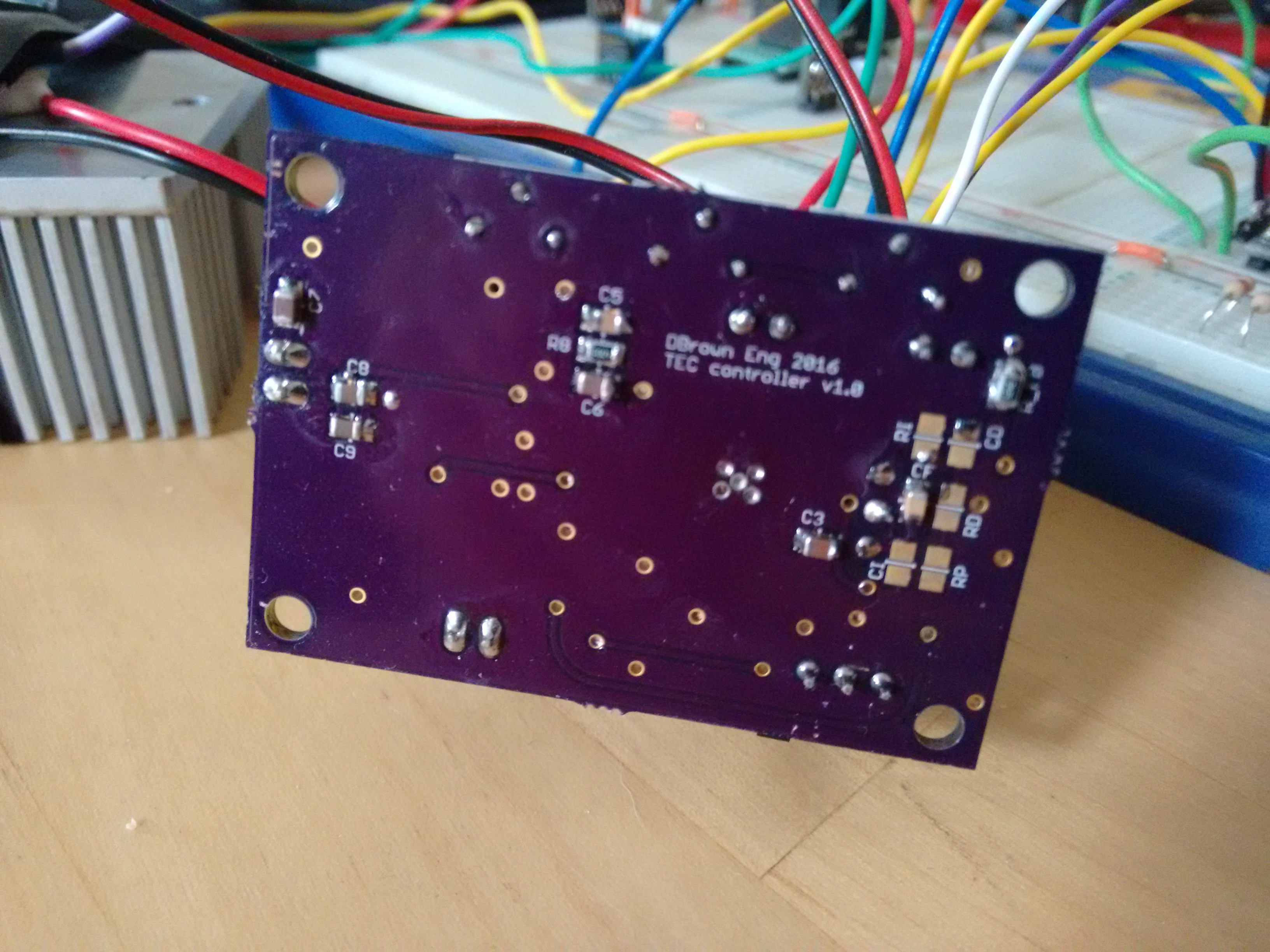 Underside showing unpopulated PID components for when the correct values have been established.
Discussions
Become a Hackaday.io Member
Create an account to leave a comment. Already have an account? Log In.