 Aron Molnar
I've been saying that the Linear FCDT is capable of measuring tilt with a really high resolution, but I didn't say a word about from where do I know that. I just only said that „After hours and hours of making an extremely precise measurements...”. It’s time to say a few words about those extremely precise measurements.
The main idea is that get a laser pointer, attach it to the test bench (picture below), adjust the bench a little bit, see how many millimeters the laser point went from the relative horizontal level on the wall (the wall-test bench distance is about 10 meters), write down the output voltage of the signal conditioner IC, compute the tilt, and do it again at least 50 times.
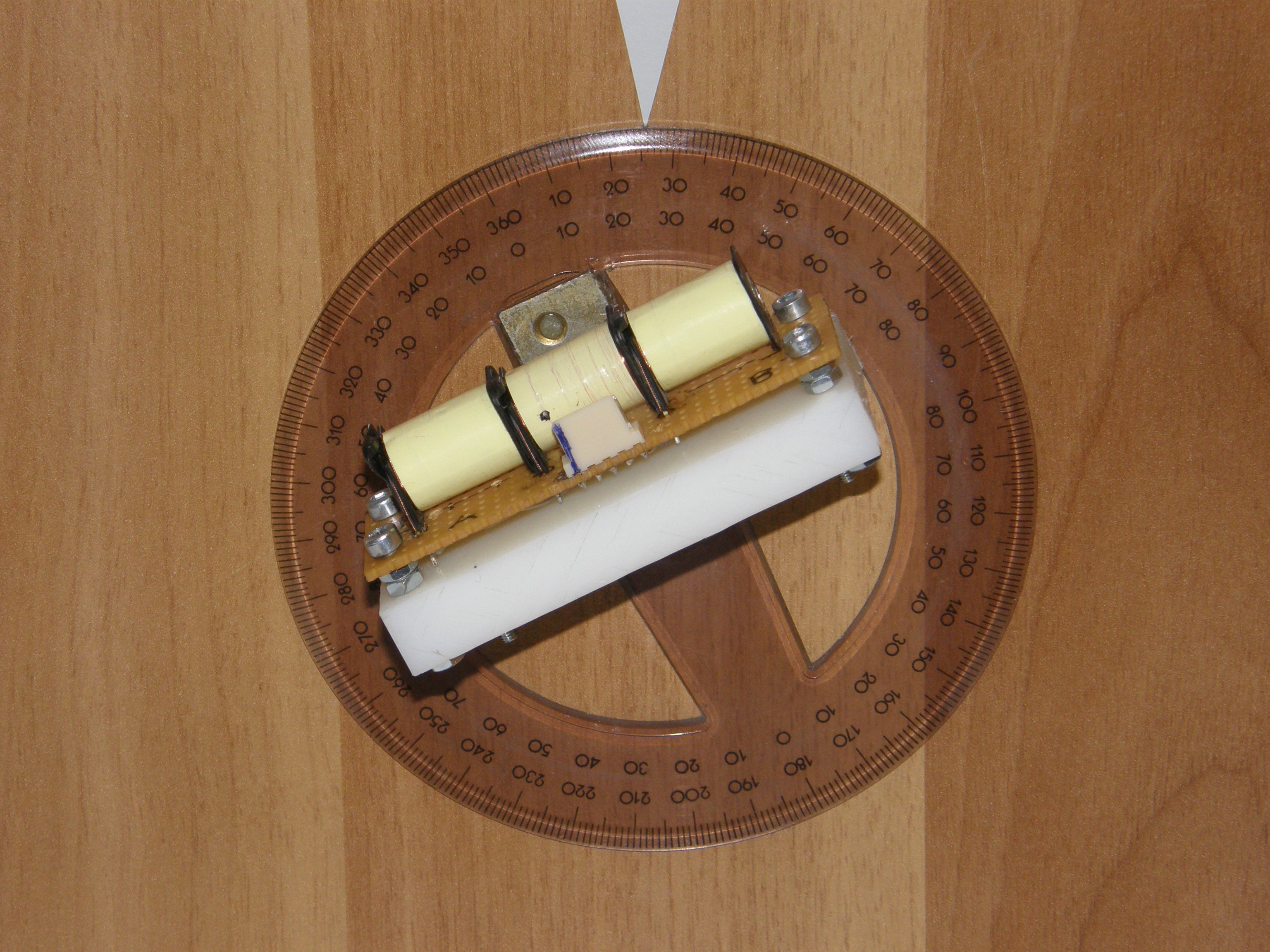
This is the test bench with the Linear FCDT (sadly, I didn’t take photos with the laser attached to it when we made the measurements):
The schematic of the measurement looks something like this:
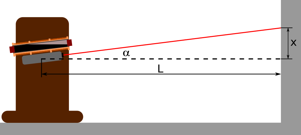
So after we tilt the sensor a little bit, the position of the laser point on the wall will change significantly, since L is great. Then we measure x, and compute the tilt with this single equation:
Next, we inspect how the output voltage of the signal conditioning circuit changed, and write down these two number next to each other: ouput of sig conditioner IC - tilt.
With this method, we can do extremely precise measurements, because L is great, so if we tilt the senor just a little bit, the chage of x will be great enough to measure that conveniently.
Discussions
Become a Hackaday.io Member
Create an account to leave a comment. Already have an account? Log In.