 Aron Molnar
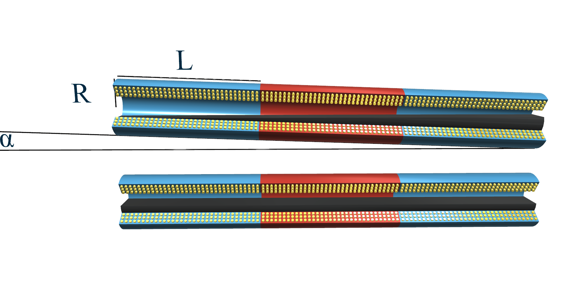
The Linear FCDT has three coils, which take place next to each other. The primary coil is usually excited with a frequency of 1 to 20 kHz and an excitation voltage range of 1 to 24 V rms.
The cell surrounded by the three coils is exactly half-filled with ferrofluid, so there is a volume of
ferrofluid in the cell. At any tilt of the sensor, there is always a volume of
in the primary coil. The spare volume of
is divided amongst the secondary coils depending on the tilt of the Linear FCDT.
Let's check out the left secondary coil on the picture above. Starting from α = 0 °, in cases of positive α tilt, the Vsec1 amount of ferrofluid will decrease.
- In the case of
tilt degrees, the liquid level can reach the outer wall, so the amount of ferrofluid in the left coil is:
- In the case of
tilt degrees, the liquid level can’t reach the outer wall, so the amount of ferrofluid in the left coil is:
Deduction of the formula can be found here: https://hackaday.io/project/11225-a-new-high-accuracy-tilt-sensor/log/47221-deduction-of-the-linear-fcdt-volume-formula
If we plot the values of Uout normalized to 1 in cases of disparate L and R rates between -90 ° and +90 ° it is noticable that the measuring range, and the sensitivity inside that, strongly depends on the L/R rate. In cases of low rate we get a relatively great measuring range, in cases of high rate we get a smaller measuring range, but higher sensitivity.

Next log: Experimental and theoretical curves of the Linear FCDT (https://hackaday.io/project/11225-a-new-high-accuracy-tilt-sensor/log/46959-experimental-and-theoretical-curves-of-the-linear-fcdt)
Discussions
Become a Hackaday.io Member
Create an account to leave a comment. Already have an account? Log In.