 novirium
So, I found one of these at Bunnings a few days ago (AUD $20):
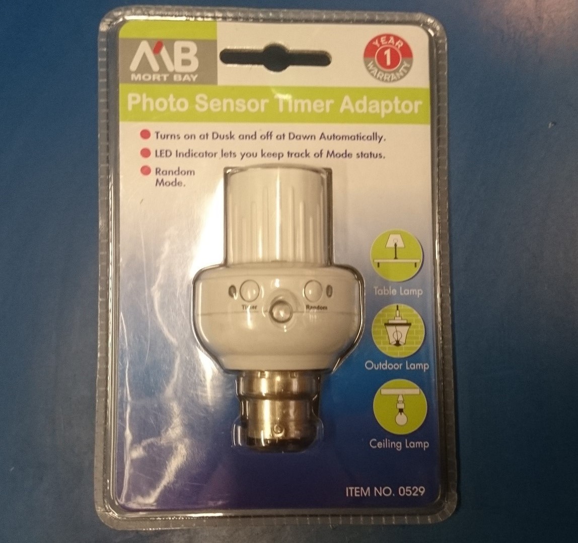
It's an inline bayonet light adapter, capable of controlling the light on a timer after dusk. I had initially hoped that it had a built in motion sensor, but it's a more basic dusk/dawn detector. Dusk/dawn detection isn't particularly useful for me personally, but I figured it'd be interesting to see how a compact(ish) commercial product handles the task of supplying power to some control logic, as well as switching the load. Depending on what the internals looked like, I even had some hope that it might prove to be a simple conversion to fit a wireless transceiver module in there somewhere.
The adapter comes apart fairly easily, a couple of screws and a bit of prying reveals the two circuit boards inside.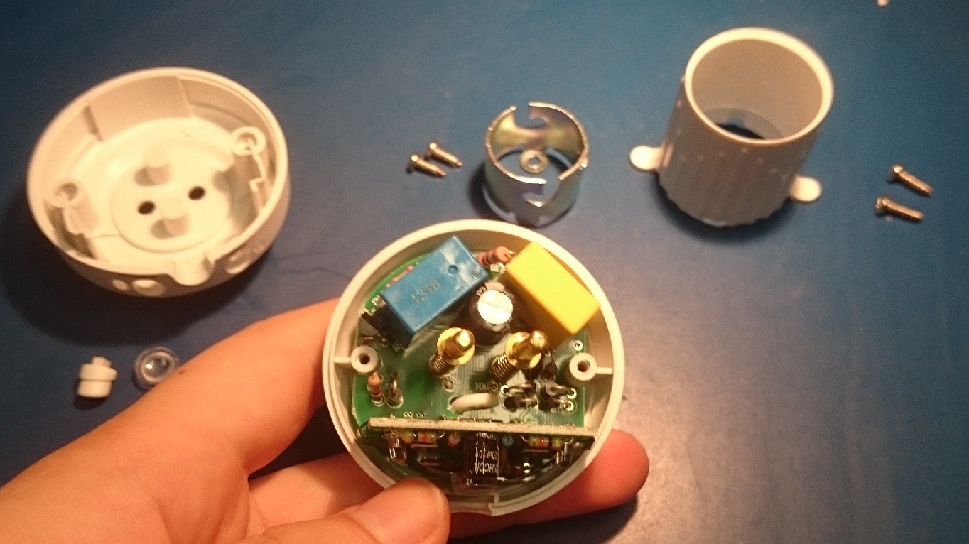
The main board shown here contains all the 240V mains lines, the load switching circuitry, and the supply circuitry for the attached control module (shown side on from the top). The construction is fairly basic, and some further disassembly separates the larger components and the control board (held in place by 4 soldered connections underneath).
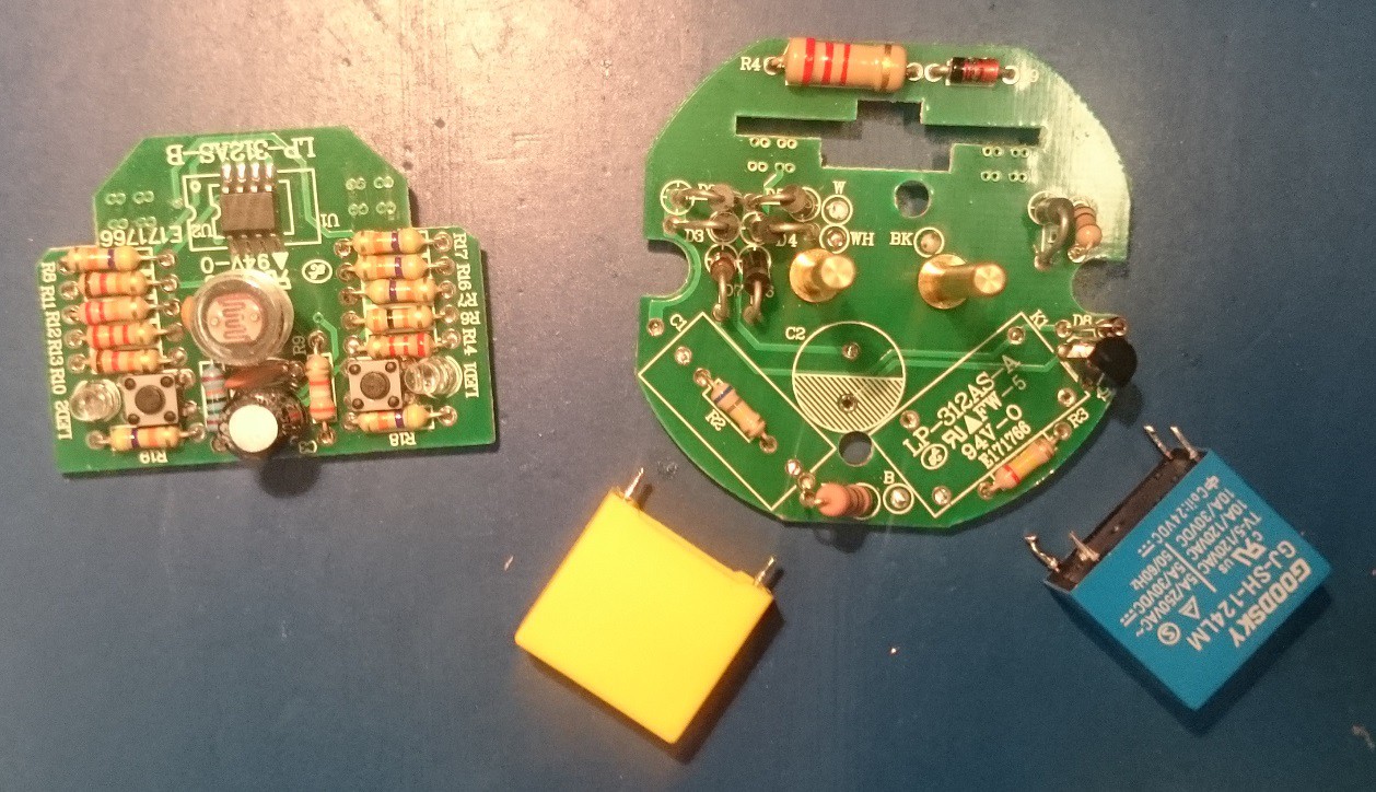
Some initial things to note: Just from a brief look over the main board, we can see that the load is being switched with a standard relay, with what looks like 12-24V driving the coil. Also visible here is a little cluster of diodes, which is very likely a bridge rectifier.
Looking at the connections to the board, this is also the first time I've realized that a bayonet socket doesn't use the the outside pins as a neutral or ground connection (as opposed to an edison screw, which does). This is actually really important, as it means that the bayonet socket isn't polarised - and any control logic we put in here has no ground reference. As such, no casual poking around in even the low voltage side of things when this is powered, as the "ground" side of the logic may well be a couple of hundred volts away from any external reference. Of course, when using a bridge rectifier this will always be a problem anyway, as your negative output will follow the lower half of the AC wave.
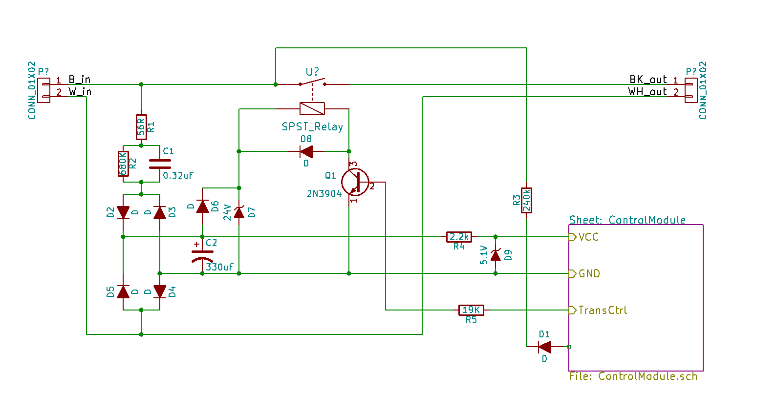
Reverse engineering the main board confirms that the diodes are a bridge rectifier, and that the second board is a logic level control module. My main interest from here was to investigate the viability of replacing the control board with something else, say an ESP8266, to quickly and easily get some wireless control happening.
Unfortunately the voltage regulation in this adapter is done very cheaply - simply using zener diodes. One 24V zener, D7, is used to regulate the voltage on the relay coil, and a second 5.1V zener, D9, is used to regulate the supply voltage going to the control board. With the voltage on C2 effectively limited to 25V through D6 and D7, the voltage developed across R4 limits the supply current to the control module to around 9mA before the 5V rail starts sagging. This can be increased a bit by reducing the value of R4, but inevitably you start hitting the limits of a resistive voltage regulator - the excess voltage essentially needs to be "burnt off", dissipating it as heat.
While this works okay for small currents, the ESP8266 is known to draw in excess of 200mA when transmitting - far more than this topology can support. It might still be viable further down the track once we start playing with low power radios (the NRF24l01 uses around 13mA while transmitting), but for now a switchmode supply is going to be necessary - that's going to have to wait until another project log though.
Discussions
Become a Hackaday.io Member
Create an account to leave a comment. Already have an account? Log In.