 frankstripod
Connecting Teensy:
It would have been typical for me just to plug a standard cable on top of the Teensy and say "there, I fixed it!" But I wanted this to be integrated into the design. The goal here is USB for Teensy, and breakout pins on top.
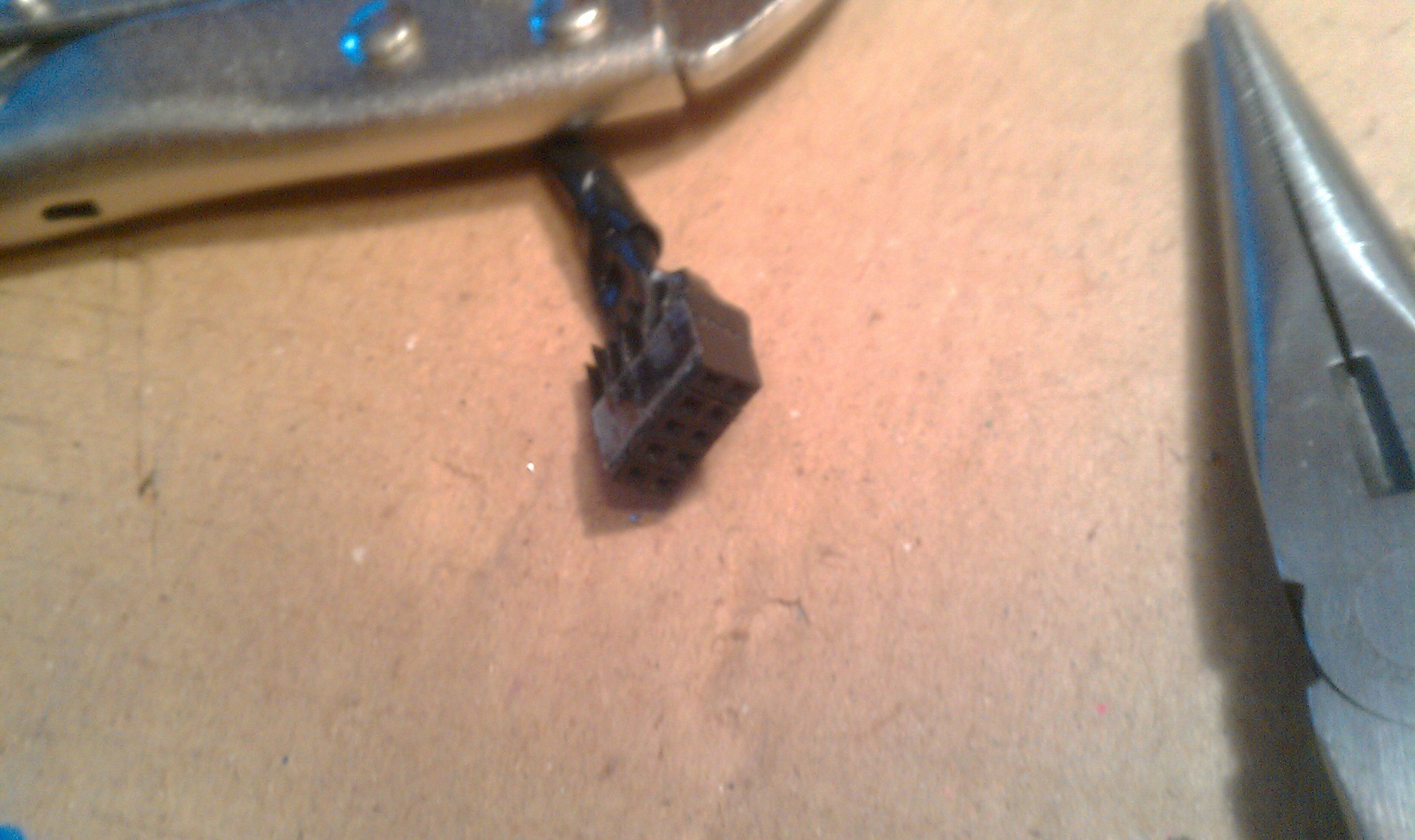
I don't know why I did this this way but this is how it went. Five wire USB cable chopped.
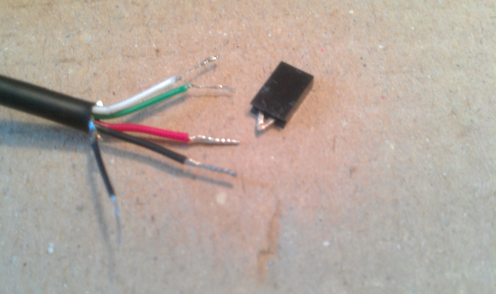
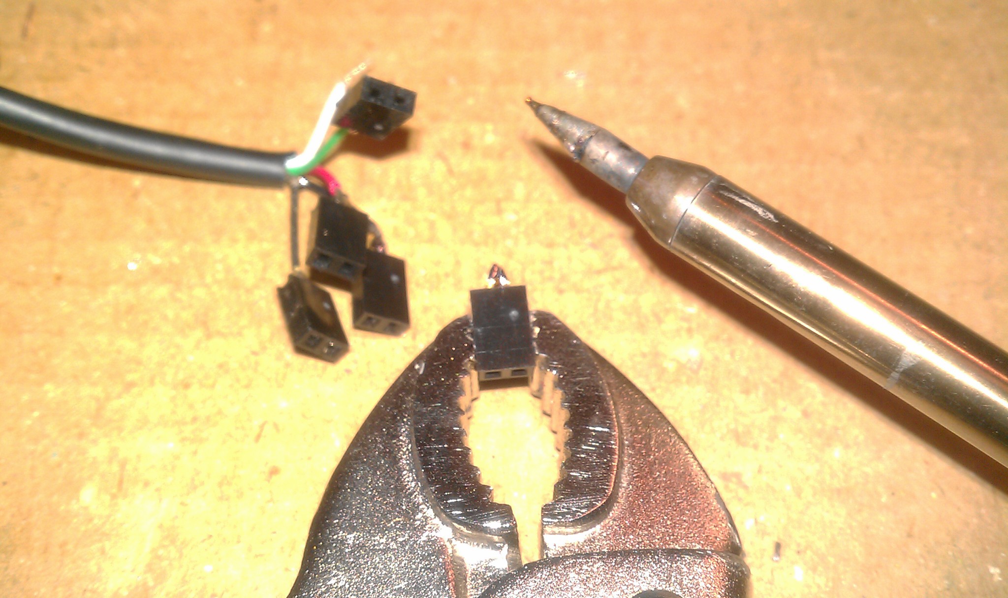
Two pin header pins bent and soldered. Each two pin jumper splits each wire; one for Teensy, one for a breakout connection on top of the trackball.
 5x
5x
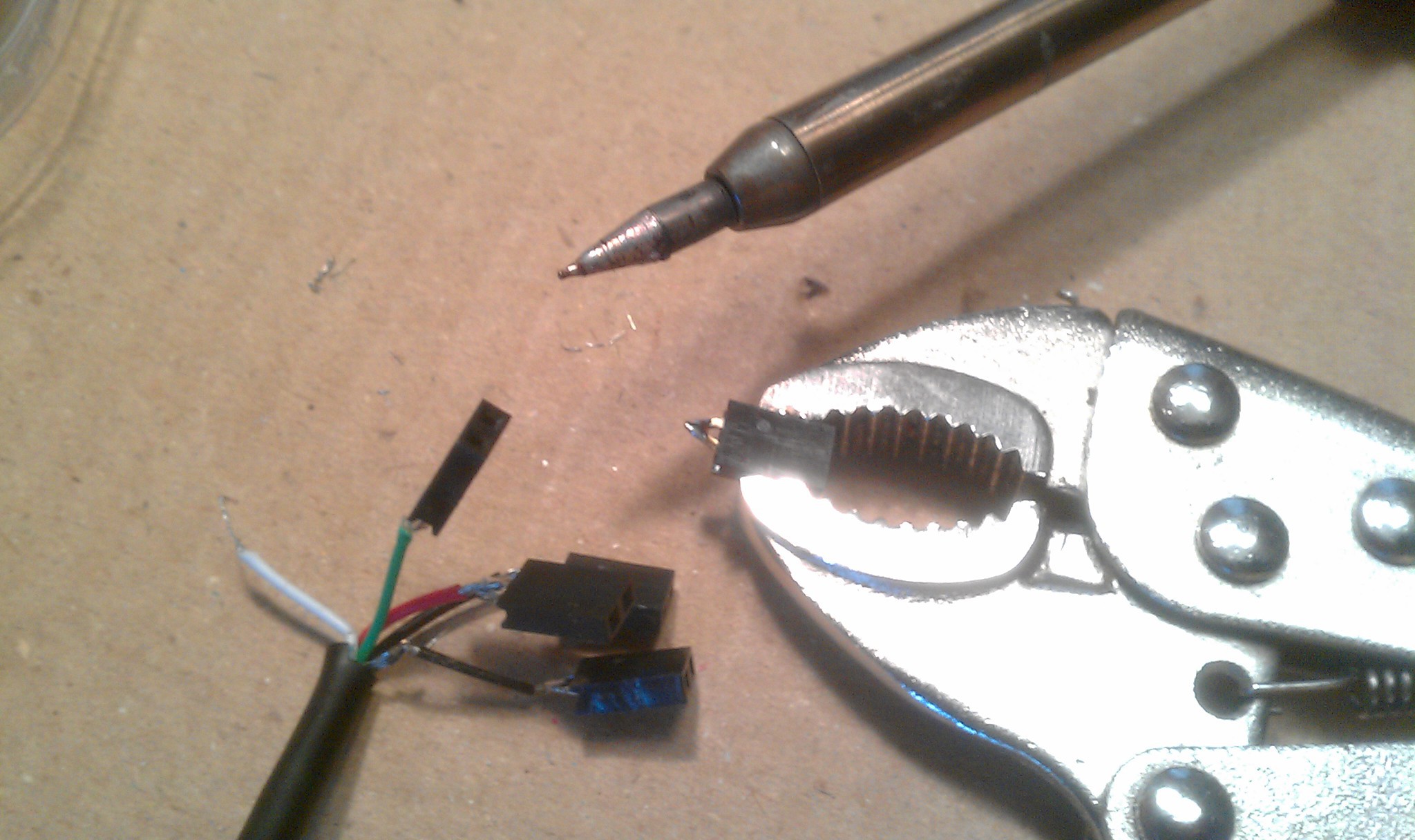 Two pin header sized squares of electric tape between each.
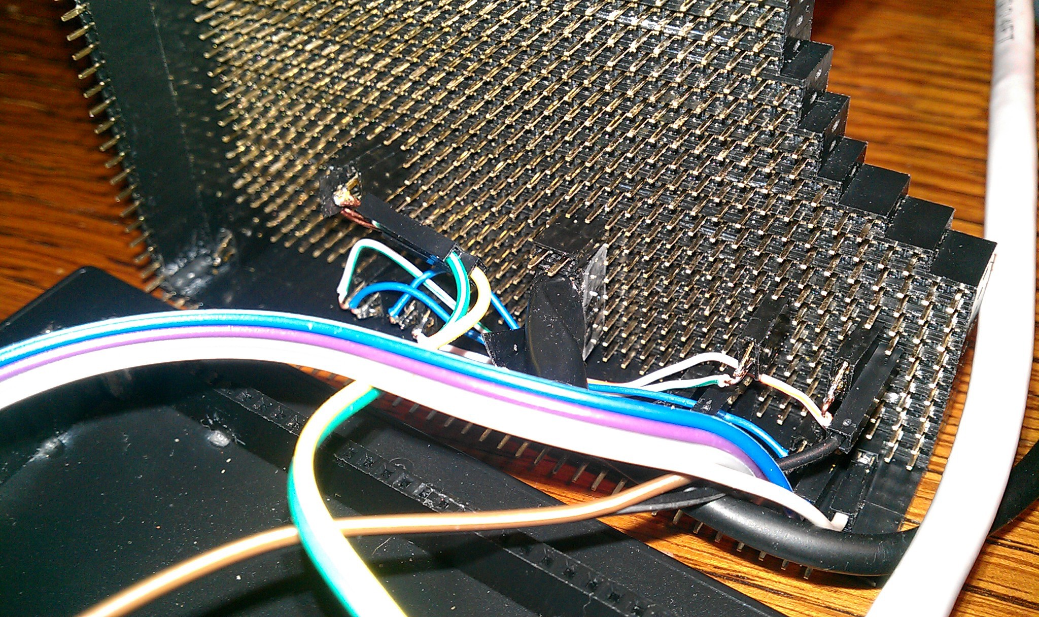
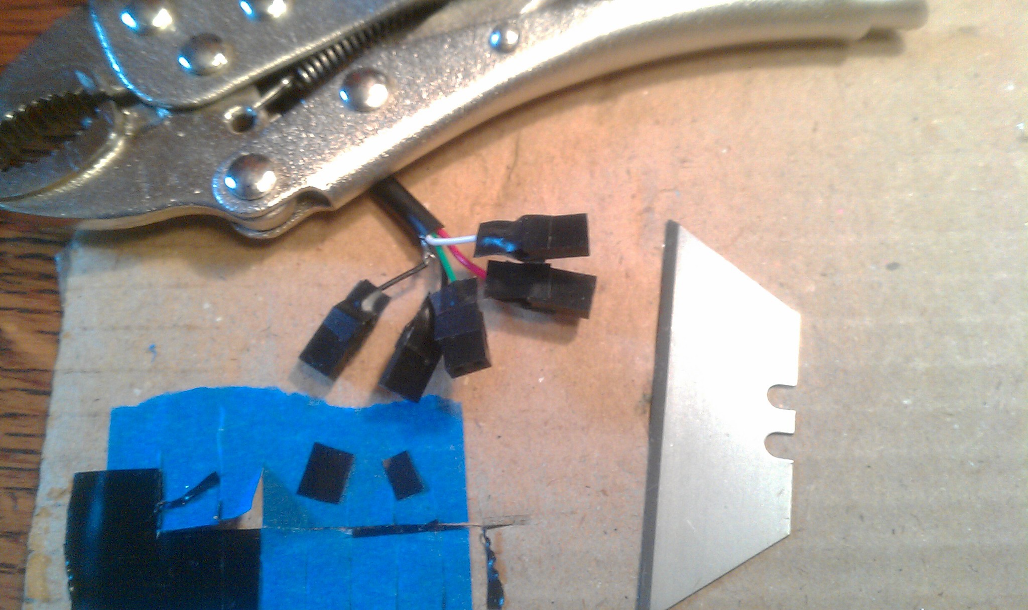 All five super glued together (held in position with two male header strips not shown.)
A rectangle of super thin clear plastic cut from the recycling bin glued along the side for support. Homemade connector:
 Plugged in underneath.
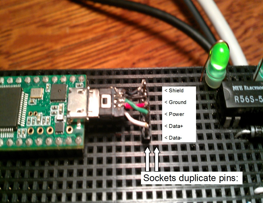
 On top I chopped an old USB micro cable for its connector. I had to be careful not to bend the delicate wires barely held on with glue. Soldered to a five pin male header, plugged into place.
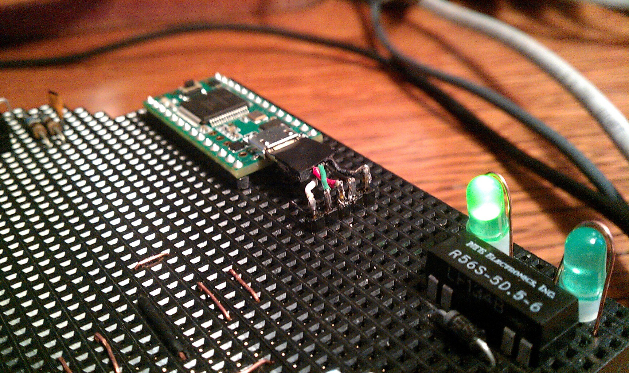 Each pin is duplicated to its corresponding female socket.
:
:
:
Secondary left and right buttons:
There are the desoldered mouse switches. 20 gauge solid wire with black insulation was used as a lever.
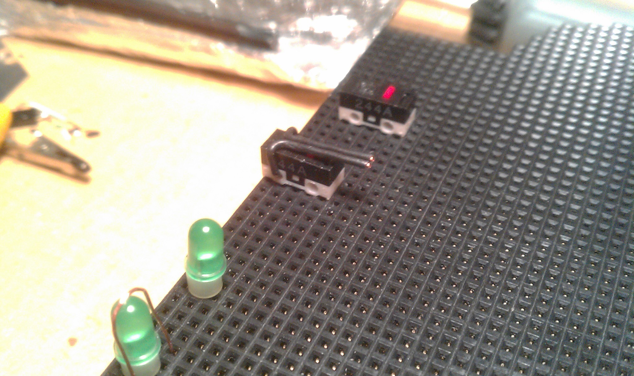 Then keyboard caps L and R were pried off of an old PS2 keyboard. The wire wrapped around the bottom, making a telegraph style button. Supper light touch and slightly flexible, but defiantly needs something like a 3D printed upgrade.
:
:
:
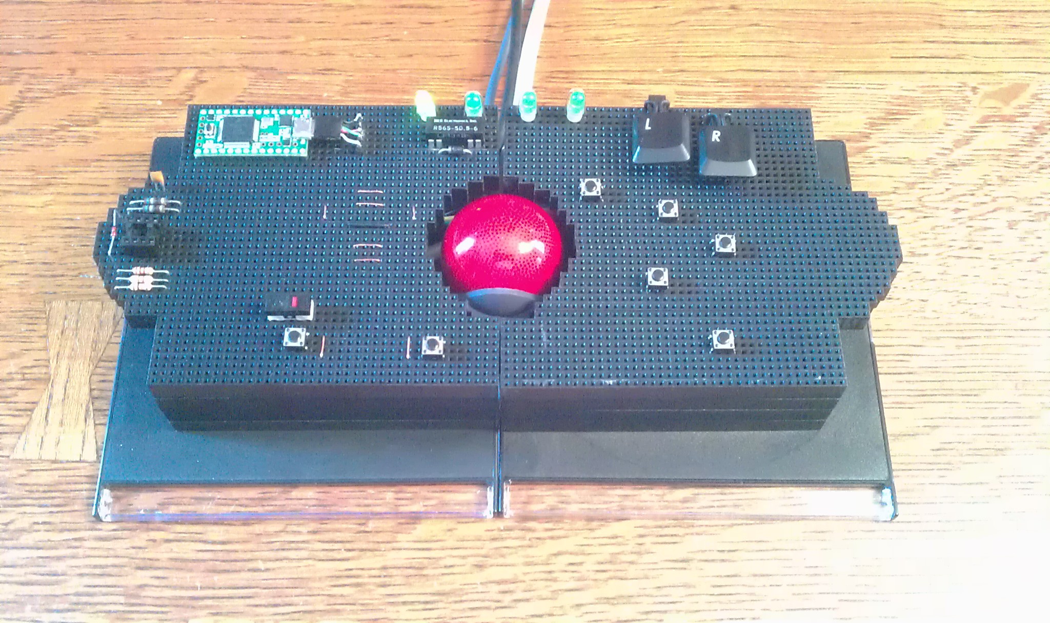
Another possible layout.
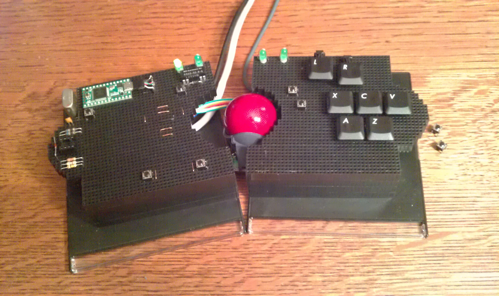
The split design conforms to my hand real well.
Touch sensor scroll wheel is back (just left of the trackball).
:
:
:
No PCB :(
You probably think I hate circuit boards. I don't. This project just turned out to be more artsy then most people are comfortable with. Not having one kept the height down; this is even slightly shorter than the original Logitech Trackball. In the back of my mind i'm subconsciously building version 2.0 which has a more solid design:
1. Circuit board holds female headers with extra long pins, soldered through the hole, then trimmed down to 7mm (6mm socket friendly + 1mm for solder).
Discussions
Become a Hackaday.io Member
Create an account to leave a comment. Already have an account? Log In.