 Elia
EliaThis project took longer than I expected to build because I didn't have a couple of parts on hand and I had my hands full with Uni work in the last couple of weeks.
Yesterday evening I finally got a chance to more or less finish this project.
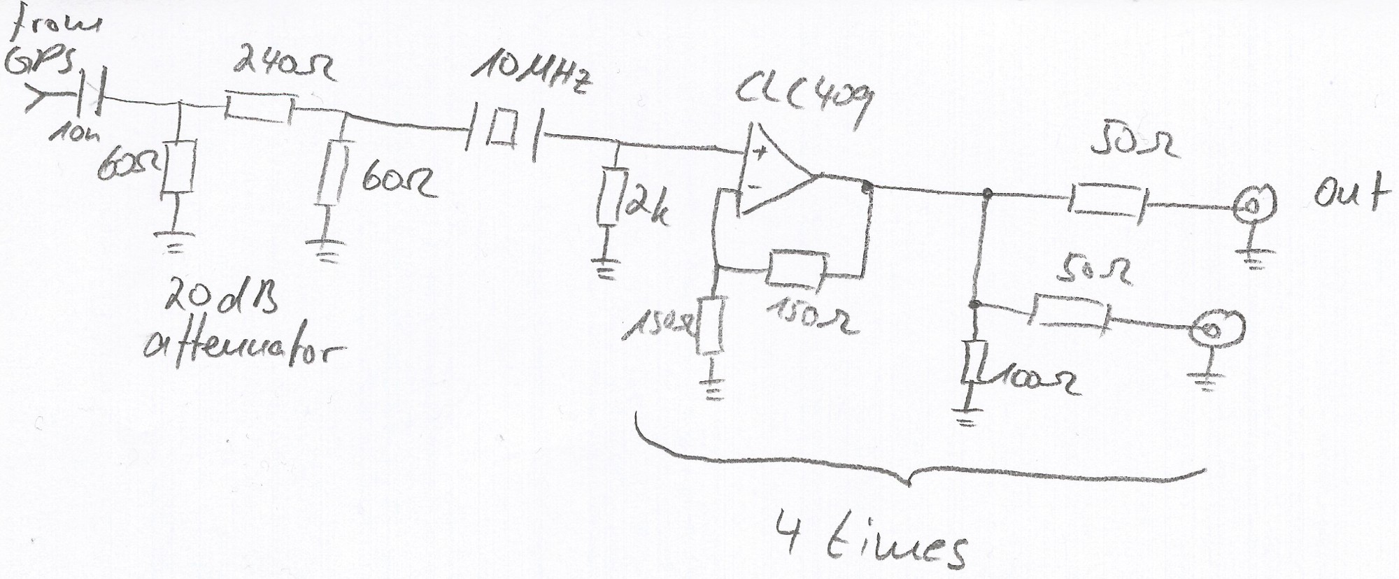
After I had posted the last project log about the low pass filter not working correctly, I remembered that I had a bunch of 10MHz crystal oscillators on hand which I could use as a high Q resonant filter. I quickly soldered something up on a piece of copper clad and didn't really bother with putting any caps etc. on there to preserve very high Q. After all I only needed to get rid of frequency content far away from the 10MHz resonance frequency, so a lower Q due to loading is not an issue.
As far as I can tell the filter is working nicely, only letting through the 10MHz fundamental and rejecting most of the jitter and higher frequency content in the input square wave. The schematic below shows what the filter looks like and also shows one output channel. The only modification to the output section is, that I have converted it to 50 Ohms output impedance.
The picture below shows how I mounted the filter and GPS module inside the amplifier case.
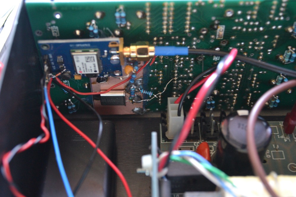
I know it looks very ugly but it works and we're at Hackaday after all.
Another shot showing the PIC18 microcontroller board that does nothing else but read NMEA info from the GPS and controls the LCD on the front. You can also see the double AA battery holder which holds the backup battery for the GPS configuration.
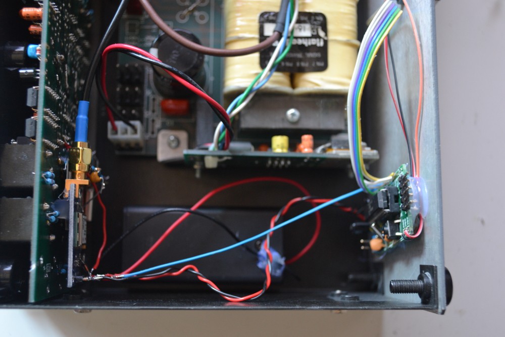
I used copious amounts of hot glue to keep that micro in place (and also to keep the leads from shorting against the case).
And finally, we're going to have a look at the output waveforms. The output gain can be set via a switch on the back panel, it has a 0.7V and 1V position. My oscilloscope has no 50 Ohm input termination option and I don't have a 50 Ohm BNC through terminator, so the output amplitude is double of what it should be.
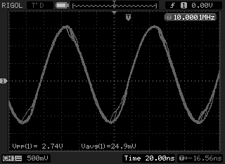
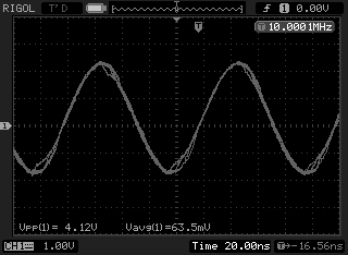
You can see that there's still a bit of jitter left on the waveform which has to do with the rather poor output from the GPS module itself.
If you need a better reference, you might want to go with a low phase noise OCXO and use a PLL to lock that to a GPS module like this. I haven't tried setting the output frequency on the Neo-7M to 1 MHz, which may yield a lower jitter output as it's an integer fraction of the 48 MHz oscillator used on the Neo.
Discussions
Become a Hackaday.io Member
Create an account to leave a comment. Already have an account? Log In.