 Ted Yapo
I recently saw the #One Transistor FlipFlop project by roelh and decided to steal simulate it.
It works!
For those interested, I'm posting the LTspice XVII simualtion files here. I'm not sure if this newer version of LTspice is completely compatible with the older one, so you might have to download the newer one (which is also free).
Here's the circuit as roelh describes it:
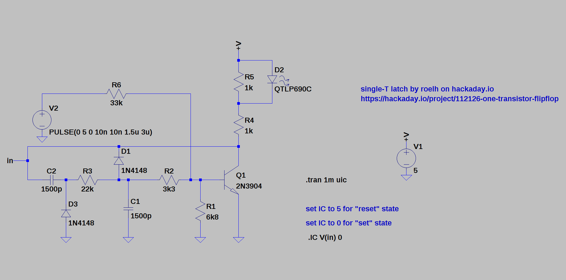
I used a clock of 333 KHz. To set the state of the latch, edit the line:
.IC V(in) 0
This sets the initial conditions at the node labeled "in" (connecting C2 and D1). Setting this value to 0V initializes the latch in the "set" state with the LED on, while using 5V puts the latch into the "reset" state.
In the set state, the current through the LED looks like:
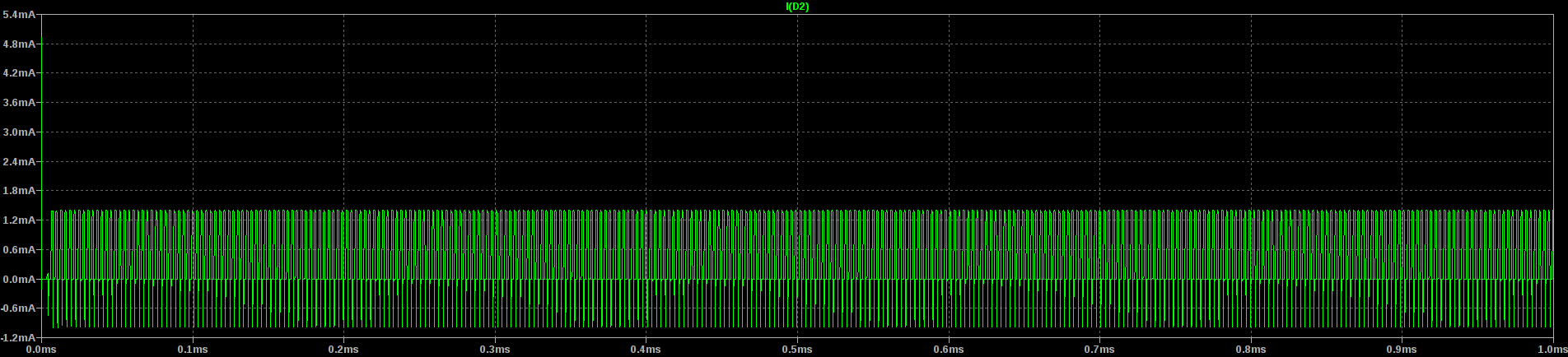
The current varies between 0 and 1.4 mA, which should light high-efficiency LEDs to a decent brightness. In the reset state, there is no current through the LED:
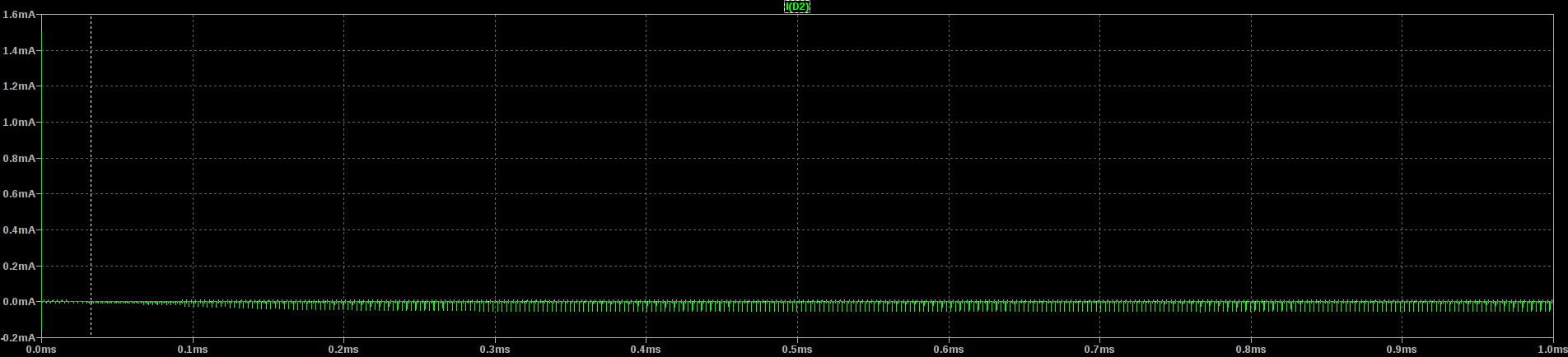
That's a latch alright.
The LED current is an AC waveform because this circuit uses both AC and DC "supplies," similar to the RF and DC supplies required for the diode-diode logic (DDL) I used in #The Diode Clock.
This is a form of frequency multiplexing that allows you to have multiple signals being amplified by the active devices at once. In that way, it's similar to the ancient reflex radio designs, where a single tube or transistor is used to amplify both RF and audio frequencies.
Discussions
Become a Hackaday.io Member
Create an account to leave a comment. Already have an account? Log In.