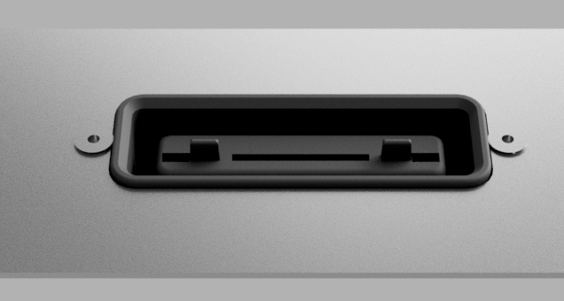
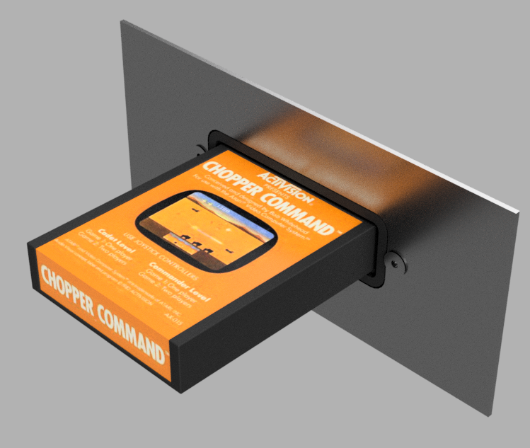
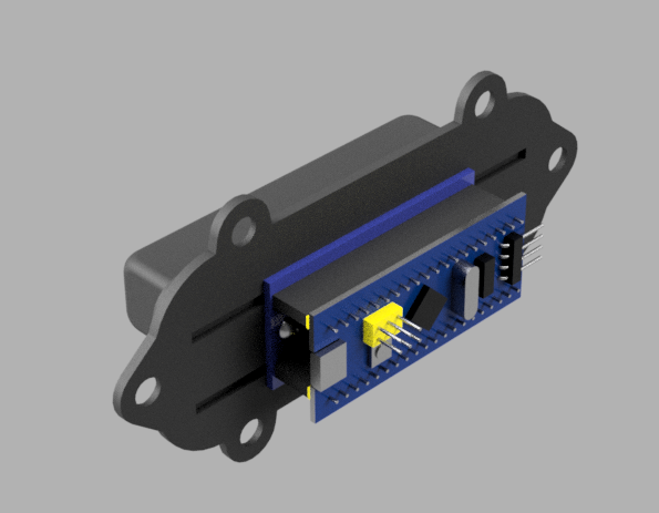
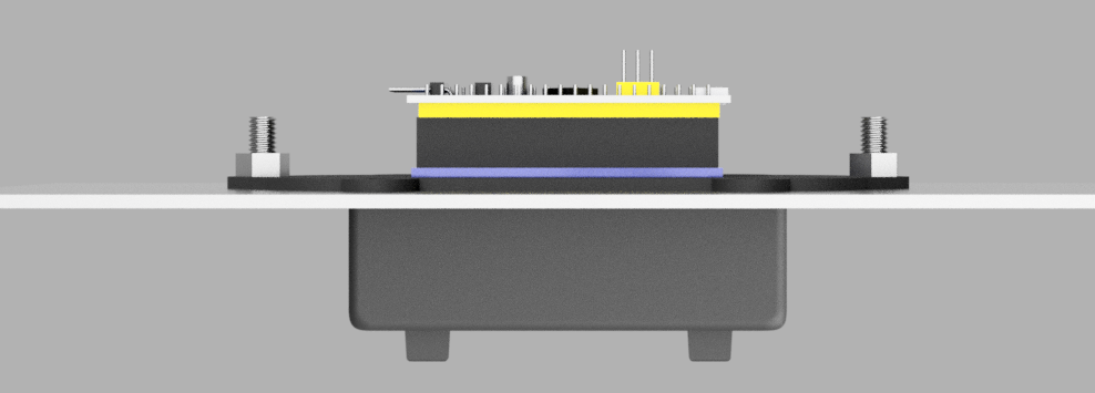
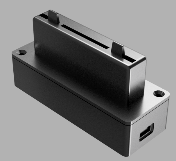
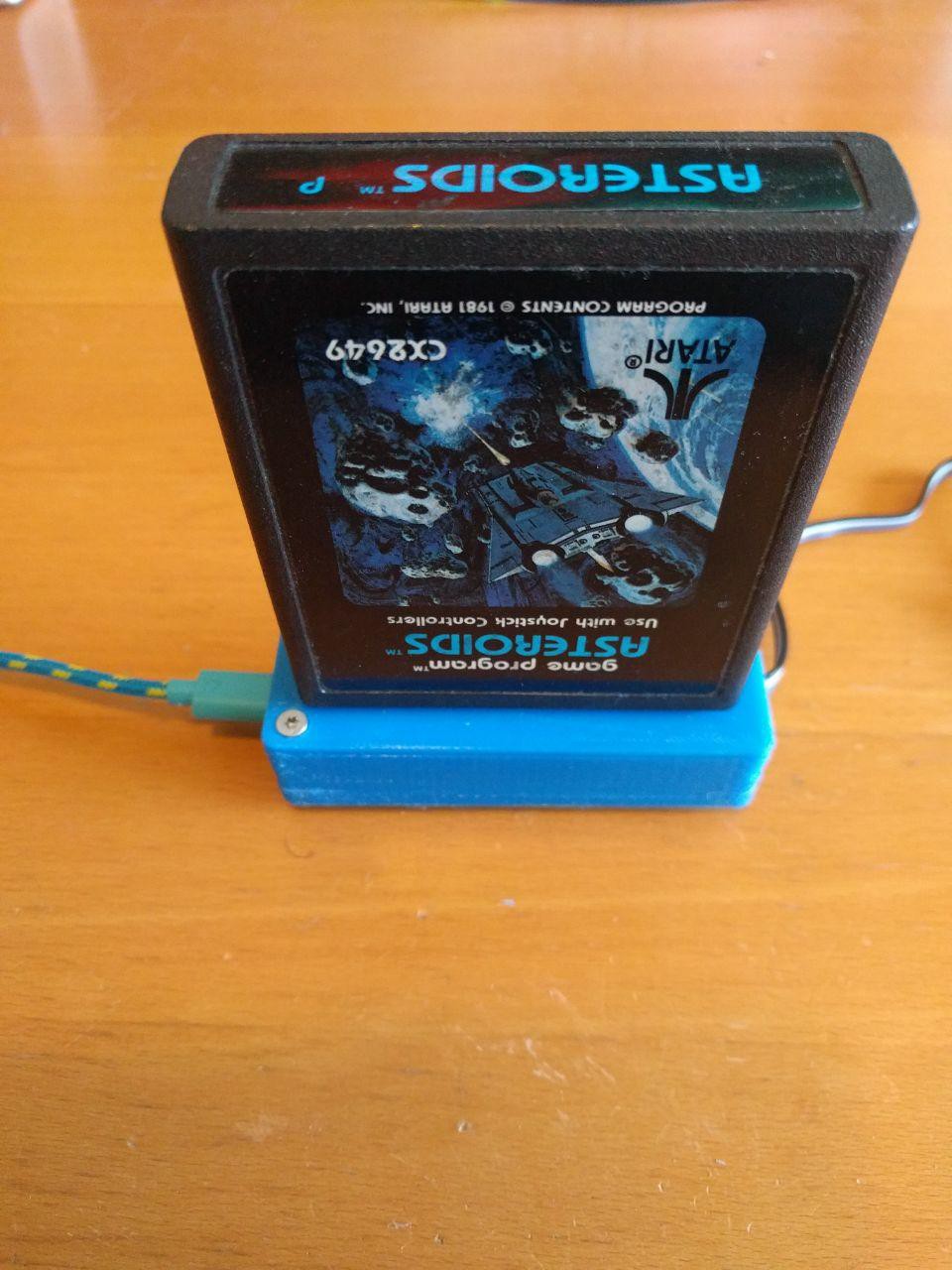
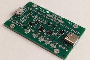
• Fancy resin printed cartridge connector

    Koen van Vliet02/12/2020 at 19:26 0 comments

    A colleague at work owns an SLA printer. He was so kind to print this connector for me. In my journey to perfection, this is a huge leap in the right direction.

  • Panel mount connector inside enclosure

    Koen van Vliet02/02/2020 at 13:45 0 comments

  • Panel mount connector proto

    Koen van Vliet02/01/2020 at 11:26 0 comments

    I have printed the new connector design. I am pretty pleased with the result, but I felt the connector was sticking out of the panel too much, so I recessed it. It looks more like the original cartridge connector of the atari2600 now.   

  • New 3d renders of the panel mount connector

    Koen van Vliet01/26/2020 at 15:43 0 comments

  • Panel mounted cartreader

    Koen van Vliet01/25/2020 at 14:53 0 comments

    Here's a preview of the new panel mounted connector design.


    I also started working on the new revision of the adapter PCB. I enlarged the holed, so the headers are easier to solder. I also reduced the size of the PCB.

  • Atari2600 cartridge reader firmware open sourced

    Koen van Vliet01/24/2020 at 20:30 0 comments

    I decided to open source the cartreader firmware. It can be found at https://github.com/keoni29/vcsreaderfw/

  • USB Bootloader

    Koen van Vliet02/07/2019 at 06:07 0 comments

    I have done some testing with the STM32duino USB bootloader. A bootloader enables the user to upgrade the firmware of the cartreader via USB without the need for a special programmer. The bootloader is active after the device is powered up or when the reset button is pressed. dfu-utlil can be used to flash on the firmware.

  • Finishing up for second proto run

    Koen van Vliet09/17/2018 at 17:15 0 comments


    Bootloader and Firmware

    The "Blue Pill" STM32 board I am using ships with a UART bootloader. I want to make the device firmware user-upgradable over USB, so I will put a USB bootloader on it instead. Currently the firmware only supports reading functions, but I can add writing support in the near future.

    Housing

    I designed the bottom half of the enclosure. It features a cutout for the usb connector and some hidden cutouts that are covered by two layers, which can be opened up with a knife to reveal debug headers, reset switch and status leds. Right now I am making these with my home printer, but I might have these made with a fancy SLA printer.

    PCB

    The PCBs I have received are usable, but I would like to do a second revision to fix some things e.g. add silkscreen on both sides, make the trough holes slightly larger.

    Software

    Some games contain extra hardware that allows for larger games. The game ROM is split up in banks of 4KB (or less), which can be selected by accessing specific memory addresses. The software only supports regular 4KB games and some 8KB games published by Atari. I will add support for some other bankswitching schemes, but I cannot test all of them with physical cartridges. Kevin "Kevtris" Horton made a list of atari games and which bankswitching schemes they use. See Kevtris List of Atari2600 games. (This is really impressive)


    Edit: Here are some pictures of the printed housing.

  • Assembly and setting goals

    Koen van Vliet09/08/2018 at 10:35 1 comment

    The assembly includes:

    • A two part housing
    • An STM32 board
    • An adapter PCB
    • Fasteners

    Housing

    The housing consists of two parts:

    • Top part, which interfaces with the cartridge
    • Bottom part, which encloses the electronics

    I have not designed the bottom part yet, as it is not required to test the functionality. It merely serves to protect the electronics. The two halves will either snap together or be fastened using self tapping screws.

    The housing is 3d printed. I can print these at home, order them from a third party or users can choose to print their own. STL files will be available.

    STM32 board

    I chose to use a pre-built STM32 board, which should require less hand soldering than a custom PCB. The STM32 blue pill boards are very cheap, however they require some work to get them to function properly. The USB connector is soldered on very poorly, so I had to add some more solder to make it stronger. The USB pullup resistor R10 has a wrong value of 10k and I replaced it with the correct 1.5k. I have had issues in the past with the programming header, so I reflowed those pins while I was at it. The boards come without populated male headers, so I soldered those on.

    Adapter PCB

    A few weeks ago I ordered adapter pcbs, which connect the STM32 board to the cartridge connector. These just arrived and I soldered up a proto.

    Putting it together

    The first thing I noticed when putting the thing together was the yellow jumpers sticking out on the bottom. (I could have foreseen this in CAD.) If I flip the board around I save a few mm. This means the housing can be smaller -> cheaper.

    Goals

    • Finish housing design
    • Improve manufacturability
    • Release STLs
    • Release software
    • Write and release user manual
    • Build 8 units

  • Boards Ordered

    Koen van Vliet08/21/2018 at 10:52 0 comments

    To connect the STM32 to the cart edge connector I designed a small adapter board. It is designed to screw into the back of the connector housing. It contains some female headers. I placed a solder jumper to connect shield ground to the ground plane. It would be possible to place a small surface mount inductor here. I have ordered 10 of these PCBs, which contain 40 adapter boards in total.

    Cartridge Reader Assembly
    Cartridge reader assembly with the adapter PCB (green) attached to the connector housing.
    Panelized PCB
    A panel of 4 adapter PCBs