 Ever
EverThen proceed to explain each of the modules responsible for acquiring the different bioelectric signals to be sensed.
Sensor 1: ECG
“The ECG signal is one of the most important biosignals that can provide a great amount of information in medical and fitness applications. It senses the electrical activity of the heart during its muscular contractions. During the heartbeat, the muscular cells on the hearth surface depolarize their membrane. The resulting potential differences can be detected using surface electrodes placed in a proper configuration and a low noise signal amplifier. The typical frequencies of ECG signals go from 0.01 to 250 Hz and the amplitude is lower than 5 mV” (S.Benatti, B.Milosevic, M.Tomasini, E.Farella, P.Schonle, P.Bunjaku3, G.Rovere, S.Fateh, Q.Huang, L.Benini)
There are multiple ways to acquire an ECG signal, for this device choose to use the AD8232 chip which has great advantages and can also be powered with a voltage of 3.3V.
The AD8232, from Analog Devices, is a conditioning IC for applications of ECG measurements and other biopotentials. It is designed to extract, amplify and filter the small bioelectric signals in the presence of conditions of noise.
The AD8232 has the ability to implement both a high-pass filter of two poles, as well as a three-pole low-pass filter for the elimination of noises; for this it has internal amplifiers elements attached to the architecture of the instrumentation amplifier. Also, to improve the CMRR, it has a special amplifier for the reference measurement (right leg).
Some technical characteristics of the AD8232 are:
- Supply voltage: 3.3 VDC
- CMRR of the instrumentation amplifier: 80dB
- Gain of the Instrumentation Amplifier: 100
- Input impedance in differential mode: 10GΩ
- Operating temperature range: [-40, 85] ° C
- It has a spectral noise density of 100nV for F = 1KHz, 12uV for F = 0.1Hz at 10Hz, 14uV for F = 0.5Hz at 40Hz and a differential voltage of up to 300mV.
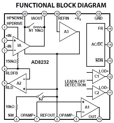
Figure 1. Functional block diagram.
The acquisition of the ECG signal is essential to diagnose abnormalities cardiac. The electrical signal of the heart has very strong characteristics and an accurate acquisition system covering all the peculiarities of the ECG signal should be designed.
The first is that the ECG frequency is between 0.05 and 100 Hz, sometimes up to 1KHz. Since the signal is very weak (approximately 1 mV peak-to-peak), it must be amplified. Besides, the instrumentation must have a high capacity to reject common mode (CMRR), normally in the range of 80 to 120 dB. To prevent small ECG signals are loaded on the skin, the ECG must have at least 10 MΩ impedance entry (Webster, Volume 3, 2006, 40-41).
Design Implementation:
The circuit for the acquisition, digitalization and transmission by Bluetooth of the signal consists of 3 electrodes connected to an analog front-end, this will filter and amplify the signal, a 12-bit ADC (ADS1015) and the Atmega328P that takes the signal coming from the ADC and it processes it through a set of algorithms. The communication between the board and a PC will be given thanks to the bluetooth that must be incorporated into the platform.
The AD8232 passes the signals to Atmega328P which then processes it and displays the RT waveform on the PC display.
The instrumentation amplifier that incorporates the AD8232, has a CMRR of 80 dB for a frequency range between 0 and 60 Hz (which, therefore, includes the line frequency). The input impedance is 10 G. The typical polarization currents are 50 pA, and the input offset current is 25 pA. The internal gain of the amplifier is 100.
Within this stage, an amplifier is included that allows a high-pass filtering and eliminates the direct current. This allows to eliminate the offsets of the electrodes of up to 300 mV, and also low frequency signals such as the deviation of the baseline. By connecting an RC network between the output of the instrumentation amplifier and the inverting input of the HPA amplifier, an integrator is formed that feeds back the low frequency signals to the instrumentation amplifier, eliminating them without saturating any node and maintaining the gain. Depending on how external resistors and capacitors are connected, a high-pass filter of one, two or three poles can be achieved. A greater number of poles improves the rejection to the noise of low frequency, but as a counterpart it produces a greater distortion of the signal and requires a greater number of components. In the case of the Publys plate, the filter is of two poles. In the AD8232 data sheet, some design recommendations are offered regarding the values of the resistors and capacitors that make up the filter.
Frequency Response
Standard –3dB frequency bandwidthfor patient monitoring is 0.05Hz to 30Hz, while diagnostic grade monitoring requires 0.05Hz to 100Hz or more. The analog front end must be AC coupled to remove artifacts from the electrode offset potential.
The upper and lower cut-off frequency of the system was adjusted to 0,05 Hz and 113 Hz, respectively.
To perform the calculation of the respective cut-off frequency, the tool was used: AD8232/AD8233 Filter Design Tool
This tool is super useful to define the lower and upper cut-off frequency. The datasheet recommends using several formulas to establish them, but care must be taken with the Q factor of the filter. I have experimented enough with the AD8232 and at first I only worked with the formulas, but I lost a lot of time doing the calculations and the Q factor used to leave the range between 0.5 and 0.7, this led to many times the ECG signal is saturated and is not possible to visualize it.
By starting to use the filter design tool, I was able to play with the value of the components and the Q factor to my liking, avoiding expenses and reducing design times.
The setting of the cut-off frequency higher than 113Hz instead of 100Hz is due to the values of the components, if adjusting the cut-off frequency of the filter at 100Hz would have non commercial component values.
Then I show screenshots of the design of the filters, and additionally the tool allows me to visualize the bode diagram of the output signal.
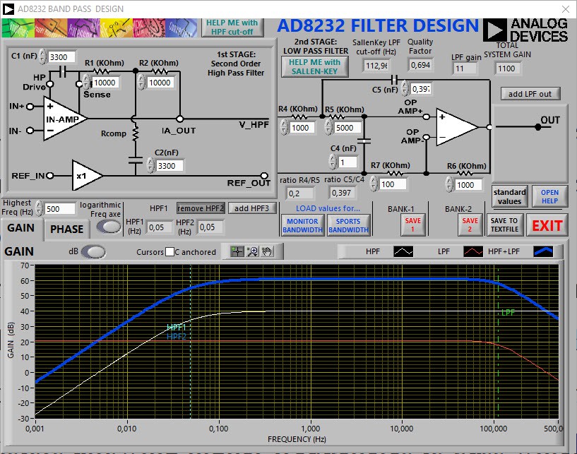
Figure 2. AD8232 filter design gain in dB.
The ECG sensor will have a gain of approximately 1100, this is due to the value of the resistors R6 and R7 in the following figure.
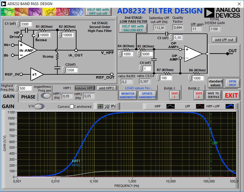
Figure 3. AD8232 filter design gain
The schematic diagram of the ECG sensor is placed below.
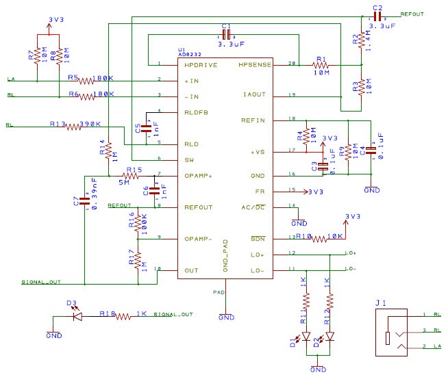
Figure 4. ECG Sensor.
Note: This configuration of the ECG sensor is fully functional, I have had the opportunity to verify it in real tests and it has a very low noise level. Then I will place the images and explain some factors to take into account to optimize the ECG signal.
Discussions
Become a Hackaday.io Member
Create an account to leave a comment. Already have an account? Log In.