0%
0%
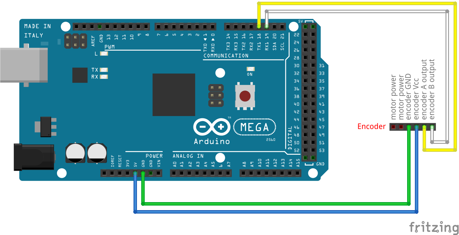
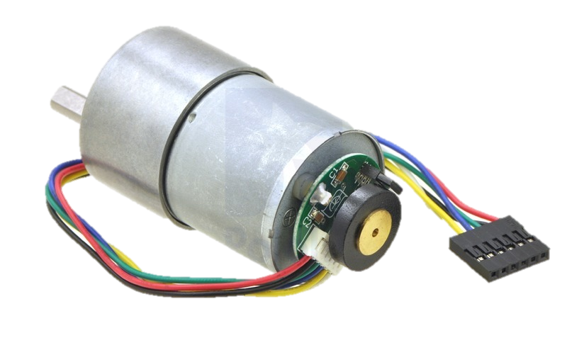
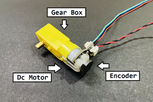
DC Motor Speed Control with PID
In this project it is aimed to speed control a standard Pololu DC motor with encoder using software based PID controller.
 Ozan Enginoglu
Become a Hackaday.io member
Already have an account? Log in.
Just one more thing
To make the experience fit your profile, pick a username and tell us what interests you.
Pick an awesome username
hackaday.io/
Your profile's URL: hackaday.io/username. Max 25 alphanumeric characters.
Pick a few interests
Projects that share your interests
People that share your interests

 Vipin M
 mrozo
mrozo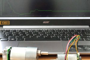
 Sagar 001
hi !
I couldn't find the final code , or you've only uploaded the encoder library ?