 Ozan Enginoglu
In this step, it is aimed to connect the encoder (just encoder not the dc motor) to the Arduino and check if it is functioning properly. We know that the encoder output for the gearbox shaft's only one turn should return 1920 so we will be checking that manually by rotating the shaft of the motor by hand.

Luckily, pin diagram of the encoder is given on the pololu web site as shown in the table below.
| Color | Function |
| Red | motor power (connects to one motor terminal) |
| Black | motor power (connects to the other motor terminal) |
| Green | encoder GND |
| Blue | encoder Vcc (3.5 - 20 V) |
| Yellow | encoder A output |
| White | encoder B output |
Motor power pins won't be used in this step but the other four pins are necessary for the encoder to function properly. Encoder GND and Vcc pins are used to power encoder circuit and encoder A and B pins are used to get feedback from the encoder. Green encoder GND will be connected to Arduino's ground pin and Vcc pin will be connected to Arduino's +5V regulated voltage output which is within the range (3.5 V - 20 V).
While connecting Encoder Pins A and B, it is important to select the pins that can be used for interrups. The reason for using interrupt pins is that Arduino should be able to get the feedback data from the encoder as soon as it changes. If the interrups are used Arduino will be able to stop whatever it's doing at that moment and get the encoder feedback first and continue. After a short search, i was able to find the table shown below.
| Board | Digital Pins Usable For Interrups |
| Uno, Nano, Mini, other 328-based | 2, 3 |
| Mega, Mega2560, MegaADK | 2, 3, 18, 19, 20, 21 |
| Micro, Leonardo, other 32u4-based | 0, 1, 2, 3, 7 |
| Zero | all digital pins, except 4 |
| MKR1000 Rev.1 | 0, 1, 4, 5, 6, 7, 8, 9, A1, A2 |
| Due | all digital pins |
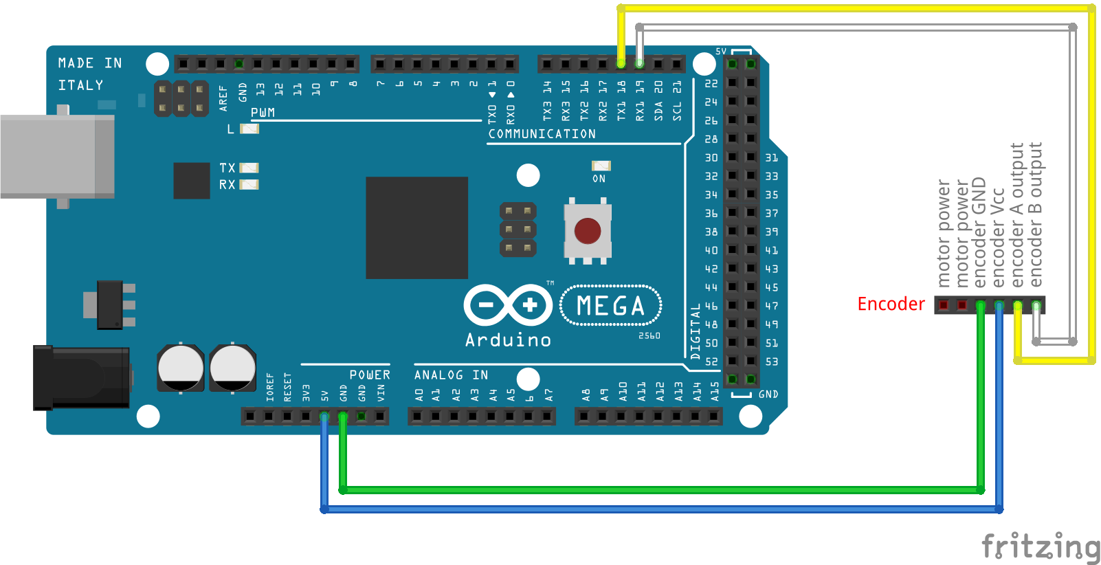
In this project I'm using Arduino Mega2560 so the pins i can use are 2, 3, 18, 19, 20, 21. Among these I preferred 18 and 19. So I connected encoder output A to digital pin 18 and output B to digital pin 19.
Pin connections of the encoder are shown in the Figure given below. As can be seen in the figure, motor terminal connections are intentionally left blank.
Discussions
Become a Hackaday.io Member
Create an account to leave a comment. Already have an account? Log In.