 Ozan Enginoglu
Standard DC motors without encoders have just two cables (terminals) to drive the motor. These terminals are used for creating a voltage difference which is directly related to motor speed. The shaft rotation speed is increased if the voltage difference between terminals are increased or vice versa.
By inverting the applied voltage to these connections, it is possible to drive the motor in the opposite direction. But unfortunately, the relation between the applied voltage and the speed is not linear and the output of the shaft rotation is unpredictable due to various reasons such as a torque applied to the shaft. In such case shaft rotation speed is reduced even though the voltage stays same. So it is clear that the speed of the motor doesn't only depend on the voltage but also to the environmental conditions.
If speed control of a DC motor is desired, another sensor called encoder is required to get the actual position and thereby speed of the shaft rotation. These information is then used to compare and if necessary correct the speed of the dc motor.
Pololu DC motor with Encoder that i've used in this project is as shown in the picture below.
Full Name: 30:1 Metal Gearmotor 37Dx52L mm with 64 CPR Encoder
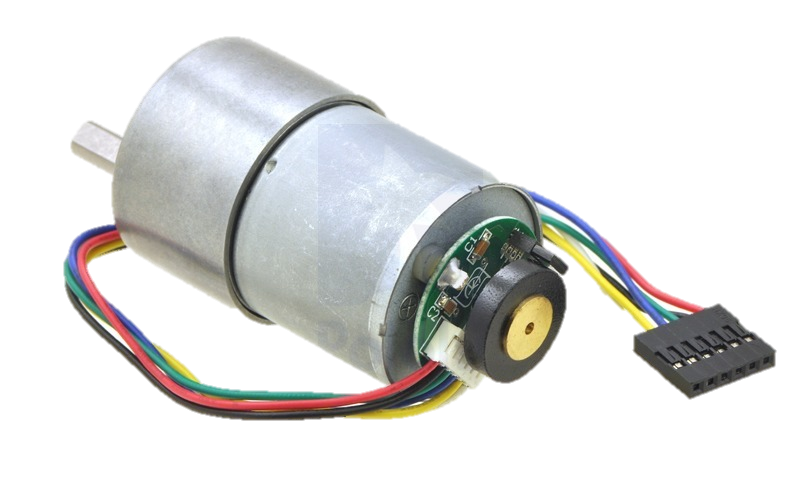
This motor has a metal gearbox with a ratio of 30:1 and a shaft with a diameter of 37 mm. Resolution of the encoder that is assembled to the motor shaft is 64 Cycles Per Revolution (CPR). This means that if the motor shaft turns one round the output of the encoder counts up to 64. But it is important to notice that the gearbox shaft is different than the motor shaft and as mentioned before, the ratio of rotation between these shafts is 30:1. So if motor shaft turns 30 times, gearbox shaft turns just 1 time. If this relation is considered; the cycles per revolution of the gearbox shaft can be calculated with the following formula:
and it is equal to 30 * 64 = 1920 CPR.
The gearbox output resolution (1920 CPR) is of great importance in this project because it is the only feedback we get from the DC motor and using this feedback we shall acquire position and speed variables to be used in PID control which will be explained in detail later.
Just like almost all complex projects, we should always prefer going through the project step by step to prevent any unknown behaviour output from the system. For this project, the steps i am planning to follow are listed below.
- Encoder
- DC Motor + Motor Driver + Encoder
- PID + DC Motor + Motor Driver + Encoder
Discussions
Become a Hackaday.io Member
Create an account to leave a comment. Already have an account? Log In.