 Joshua Elsdon
For the most part we want to avoid custom mechanical parts, as they could add significant costs to the robots. So the chassis is just the PCB itself, the axle is standard 1mm wire. The wheels on the other hand are much more of a quandary.
The current prototype is using off the shelf wheels, with the motor shaft driving them via friction. We did try making wheels of this type using rubber sheets and hole punches, this had limited success, as it was difficult to make the bore and the outer rim concentric. The high grip rubber we were using in these experiments did not take to a lathe well!
Once we moved to model aircraft wheels every thing was concentric (enough). Then we were exposed to the next issue with this system, axle positioning tolerance. Due to the extremely low power motors we are using too much pressure between the motor shaft and the wheel would cause a stall, to little would loose engagement. For the time being we have solved this issue by using a much thinner shaft material, 0.5mm piano wire, and only securing this in the middle of the PCB. By securing the shaft just slightly closer than needed and leveraging the flexibility of the shaft we could ensure a good contact between the shaft and the outer rim of the wheel.
Well the above is nearly true! In actual fact some days it works well, other days the robots only want to go in circles. This is usally caused by the motor shaft slipping. So if these things are going to be reliable we need to ditch the friction drive. If only there were some branch of mechanical engineering dedicated to transmitting torque efficiently between two round entities, Perhaps the study of some kind of meshing wheels.
After some quick research, turns out we need gears ;) . The problem with gears, and the reason we were avoided using them in the first place is the wanting to avoid custom parts, but it seems that this is now unavoidable. There are small gears that you can buy, but we need to have an additional outer rim to grip the floor. The motors we are using actually came with gears, 9 teeth of 0.3 module miniatureness to be exact. So we need to make gears that fall into some of the smallest standard gear profiles commonly available. Normal FDM 3D printers are out, long live DLP based resin printers! For reference the printer I am using at the moment is the Roland ARM-10 that is in residence at the ICAH (Imperial College Advanced Hackspace) digital manufacturing lab.
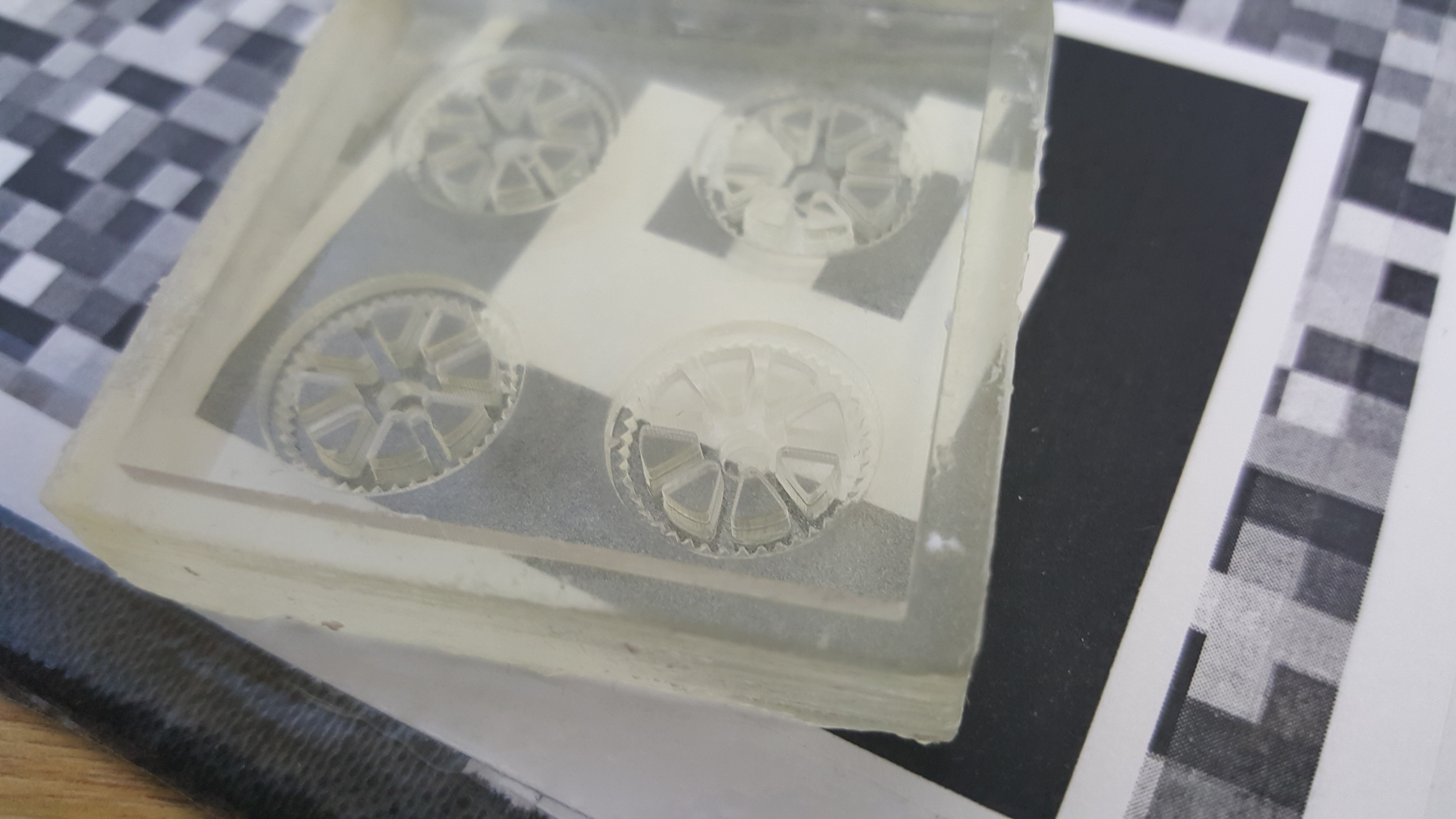
There are 2 approaches that we are trying. Printing the wheels directly with a groove for an oring to provide grip to the floor. Secondly we are trying to print the negative of the wheels and casting the whole wheel in a rubbery substance. (Ignore the fact that I ordered the wrong size orings by mistake)
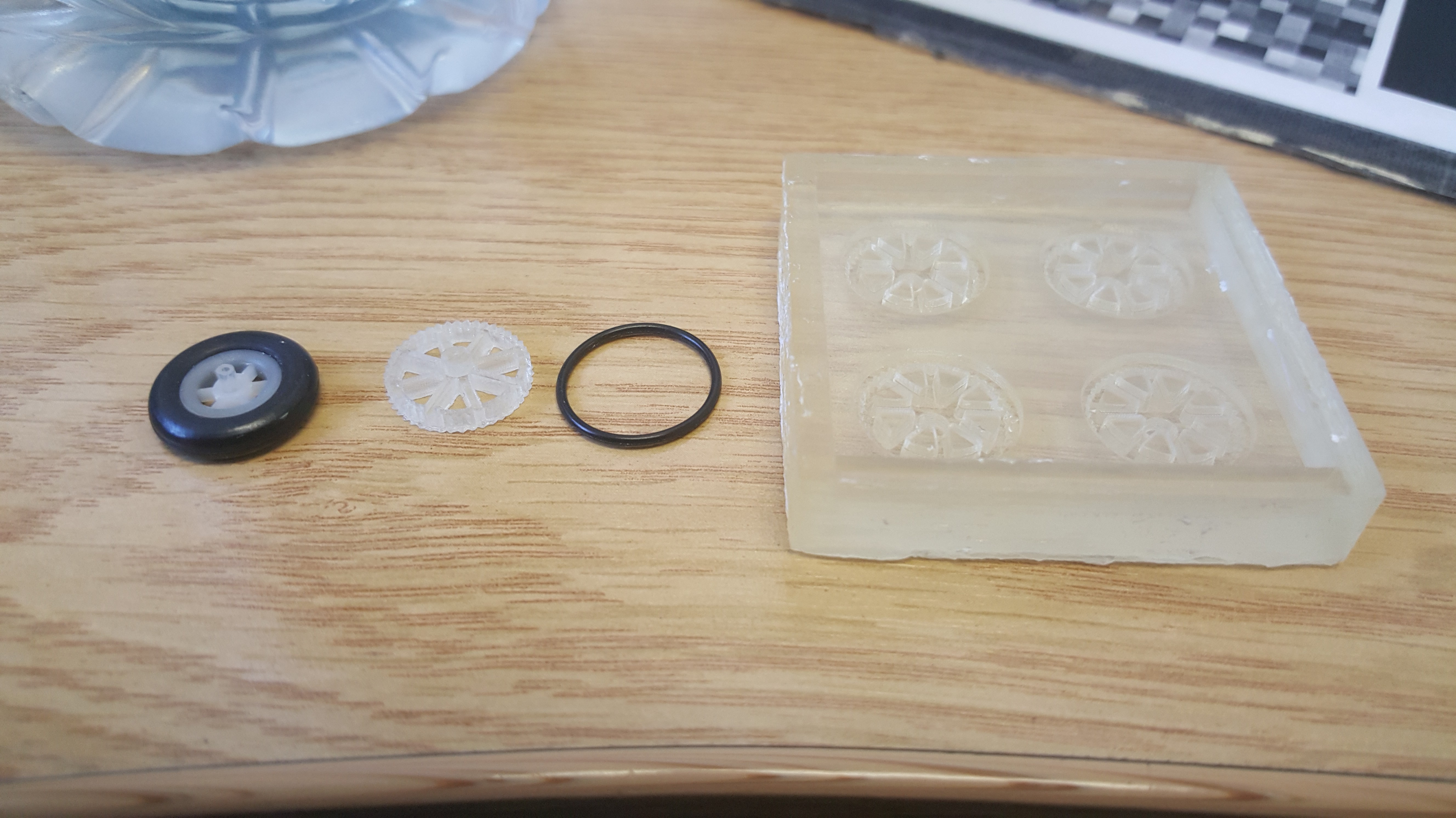
The directly printed wheel is probably workable, and we will likely be using it in the next prototype. Though there is a certain attraction to casting the wheel all in one. Eventually, when the project is a success we will need to injection mould the wheels, and I suppose you could see this simple moulding as the first prototype for that process.
Just to prove that the friction drive can indeed work well at times here is a video (upright video alert, \begin{excuse} my other hand was using a remote control \end{excuse}):
For size reference, the robot occasionally summits the small disc in the centre, which is a British 2 pence piece. (Long live the Queen and all that).
Discussions
Become a Hackaday.io Member
Create an account to leave a comment. Already have an account? Log In.