 Joshua Elsdon
We have had one robot working for a little while now, responding to manual remote control commands, the next step is to have something a little more 'swarm like''. 6 more robots is our target, and this log will show and describe the process of assembling them.
This post may also mirror many of the things said in this , as we were the ones to do the soldering section of that project, so if you want more pictures of a similar process, check there.
First you will need some PCB's. We used Elecrow for ours, their prices are good, especially for steel solder paste stencils, $18 for one with a fancy frame, nice! There are many other manufacturers that do a good job, so have a look to see which ones are quickest/cheapest delivering to your country. For this design we highly recommend using a proper steel stencil, rather than home brewing one, these parts are on the tiny side.
- Source the components, Farnel and RS are good. The full BOM will be published a little later, the design is still in flux.
- Lay a board flat on the table and line the stencil over the top. Using a credit card (that you no longer need) scrape the solder paste across the holes, then in a second pass remove the excess. There should be shiny steel visible everywhere apart from where the holes in the stencil are. The holes themselves should look evenly filled with paste.
- Lift the stencil, the board will likely stick to the bottom. Remove the board, avoiding smooshing the paste!
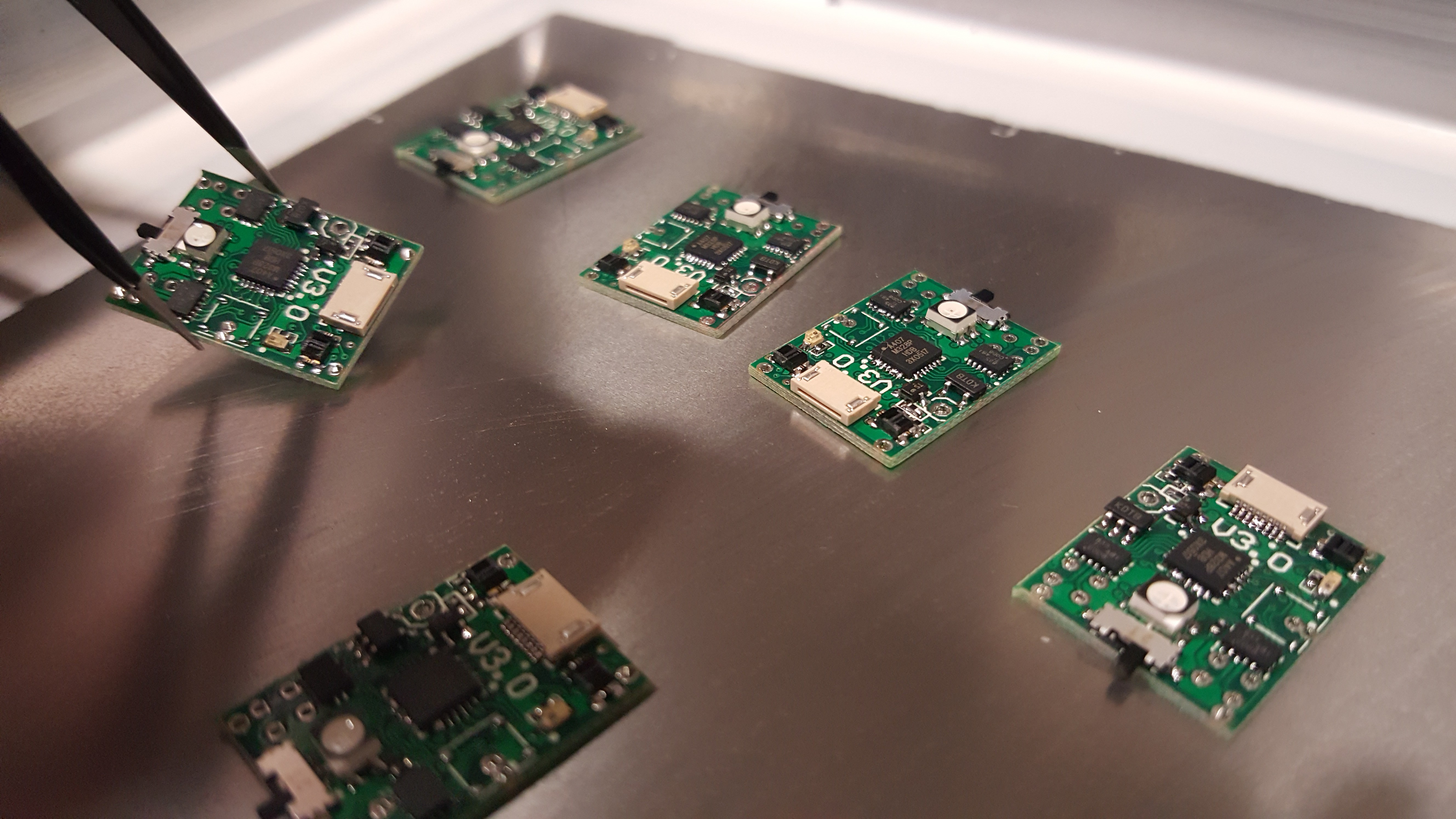
- With tweezers place all the components on the board being carful with the orientation of the ICs and the diodes, DO NOT PLACE THE BATTERY. (BOM + Circuit diagram + Board layout to come when the board is finalised)
- When all the parts are on one side, place in a SMD soldering oven if you have one. Alternatives include modified toaster ovens or a hot air gun. I would not recommend a hot plate. The board is double sided, so when doing the other side this won't work.
- When cooled flip the board and apply paste in a similar manner. The complication now is that the other side of the board is not flat. We just did the stenciling freestyle by trapping the board between the stencil and the table, though you can use shims to raise the board to allow it to be flat.
- Place the components on this side and reflow.
- Inspect carefully and remove shorts with a soldering iron and desoldering braid.
- Solder on the through hole components and the battery.
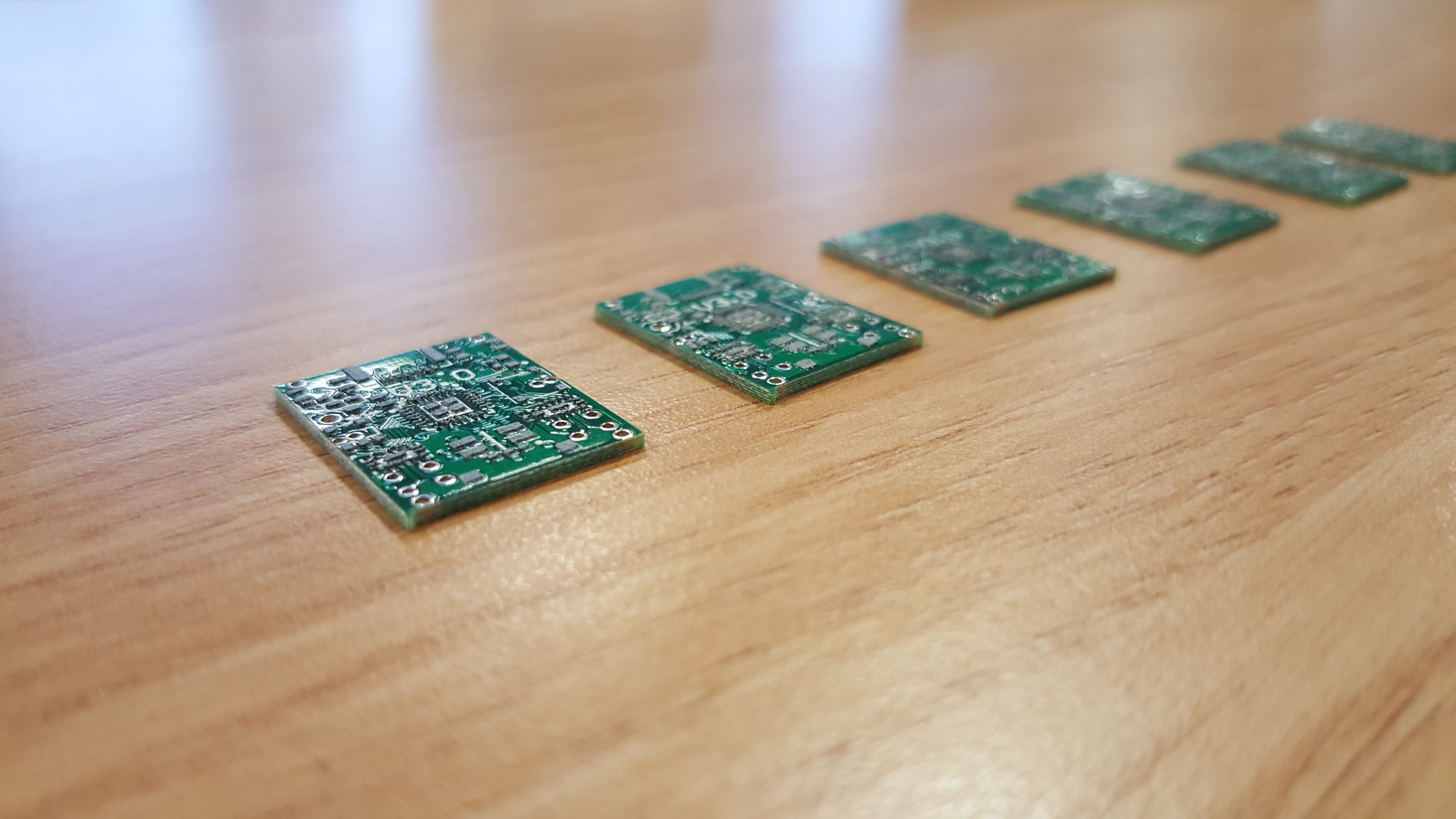
The paste should be nice and square, with well defined gaps between pads.
Go slowly, placing one variety at a time. Resistors and capacitors in this size have no markings, so if you mix them up, bad things ....
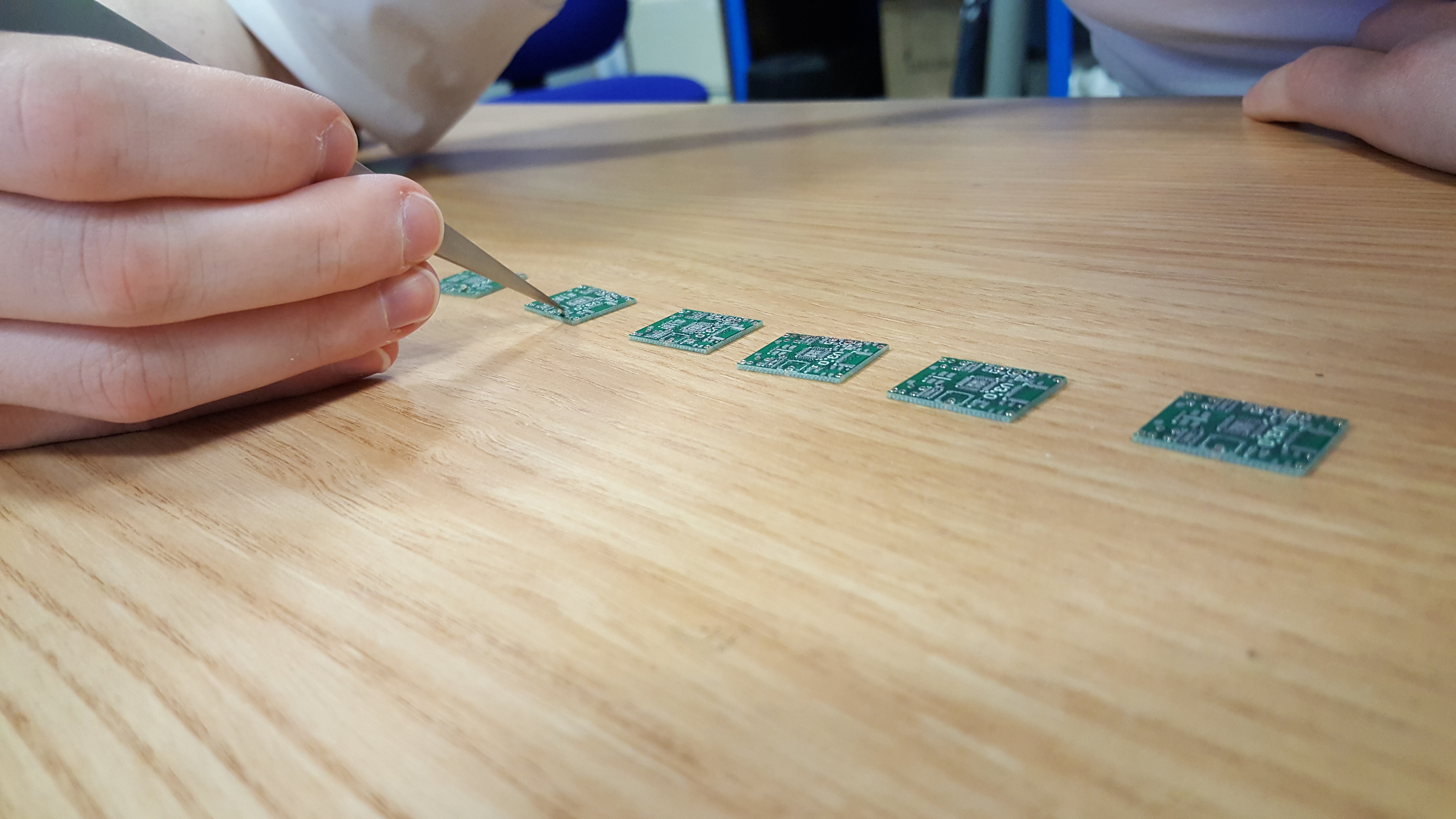
Carry them to the oven/airgun carefully, the surface tension of the paste should hold parts in place, but they are delicate!
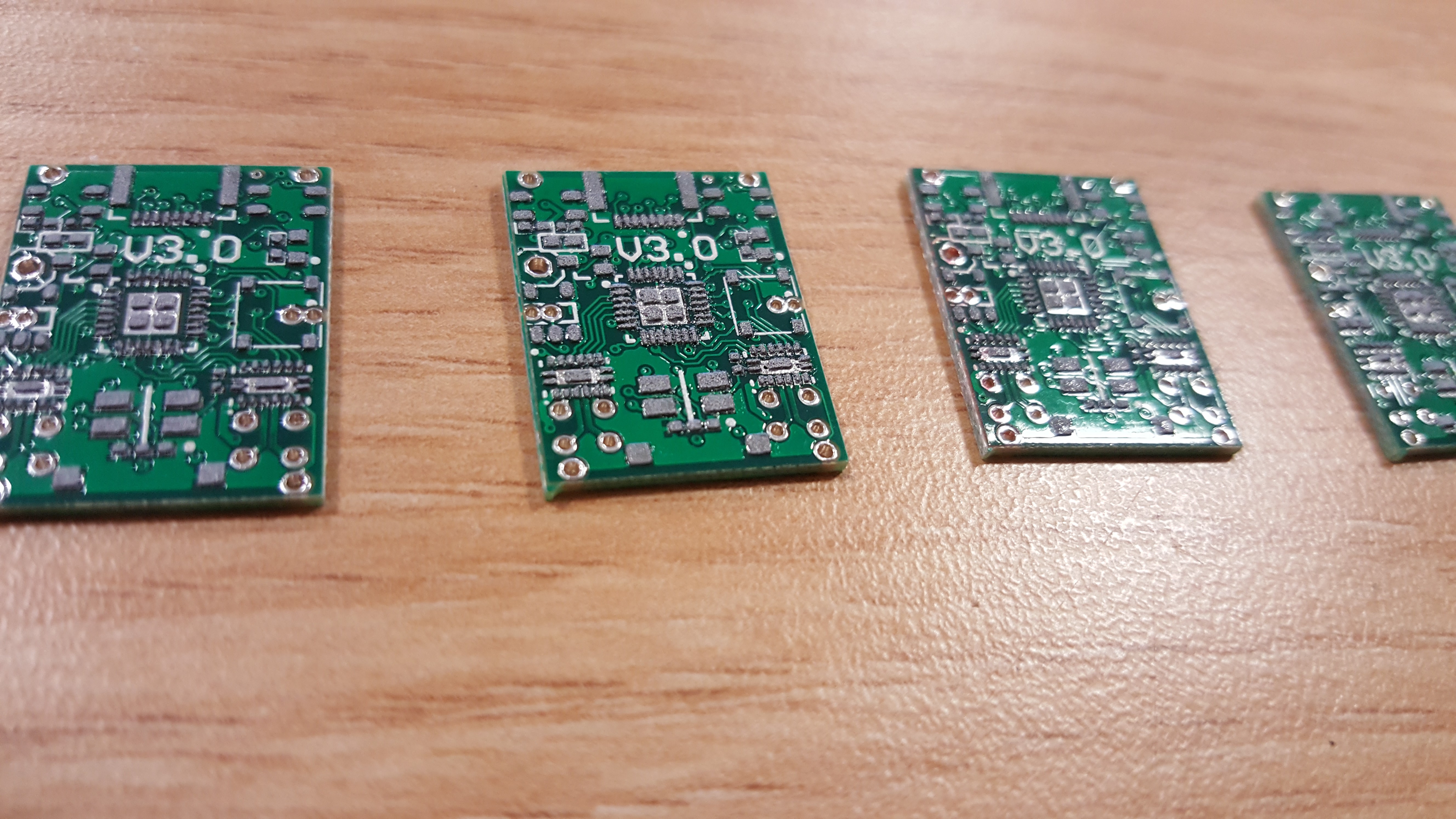
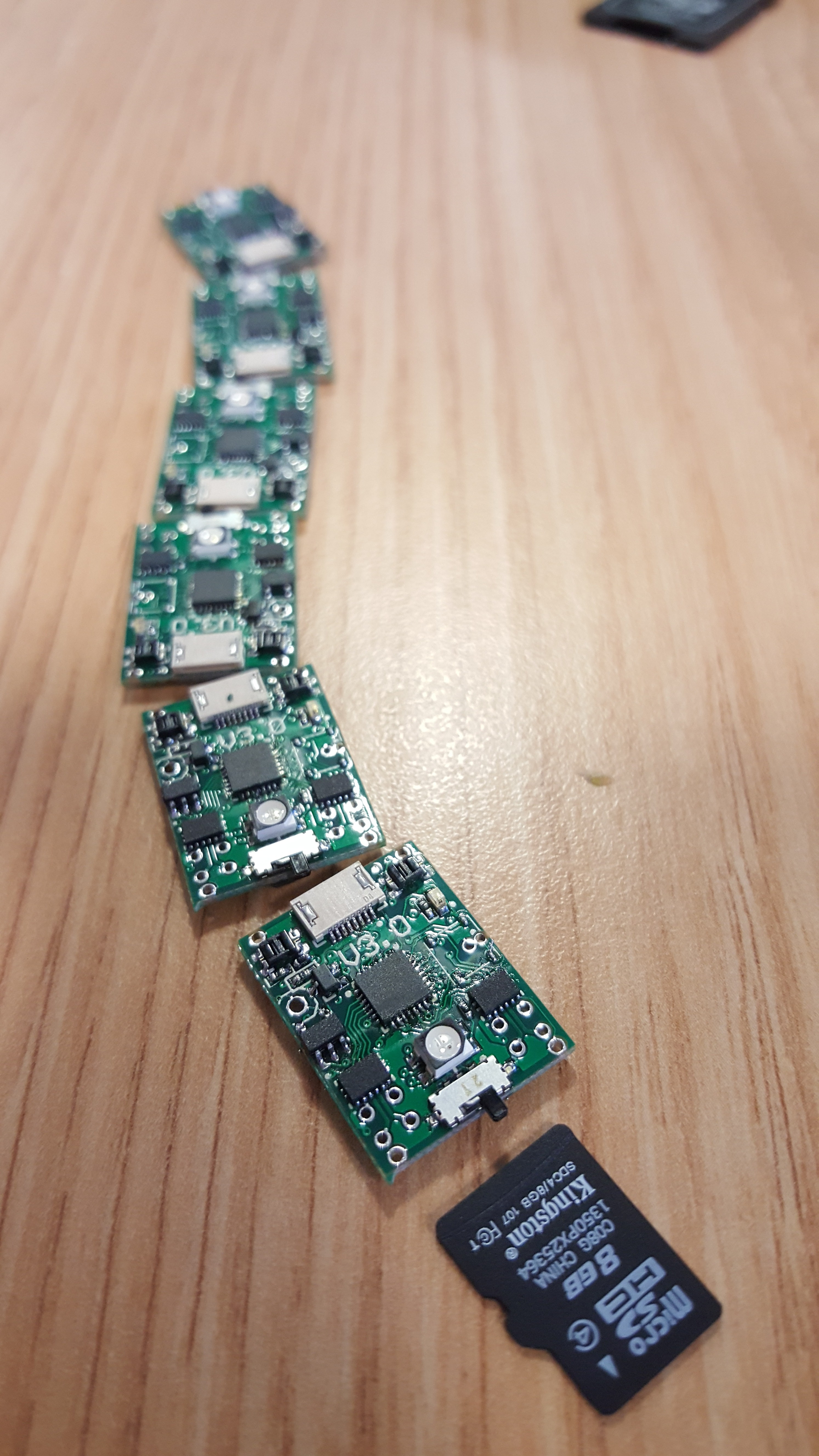
After soldering the top. There are still shorts on these boards, an exercise for the reader.
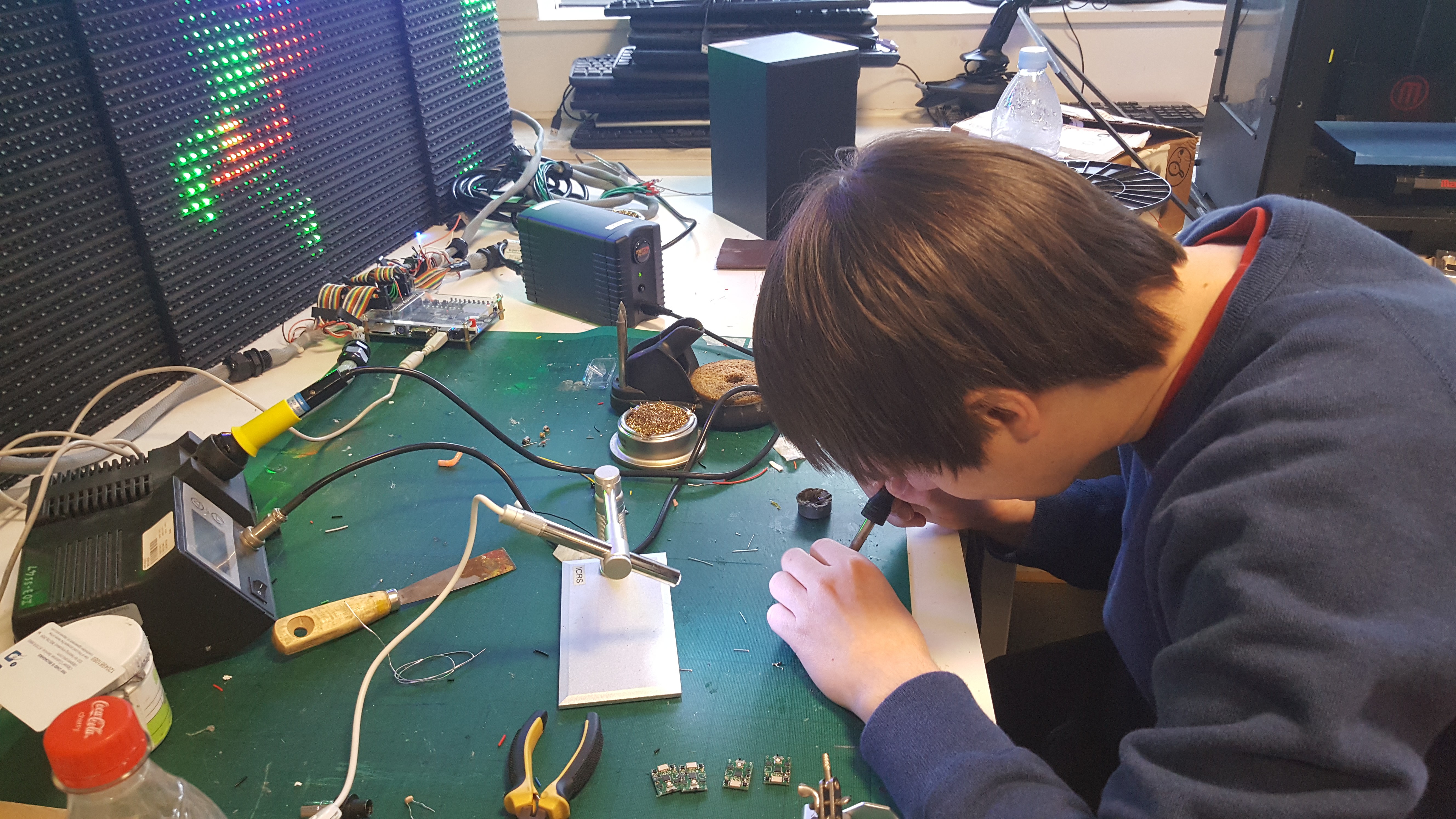
Rework the joints at your favourite messy desk.
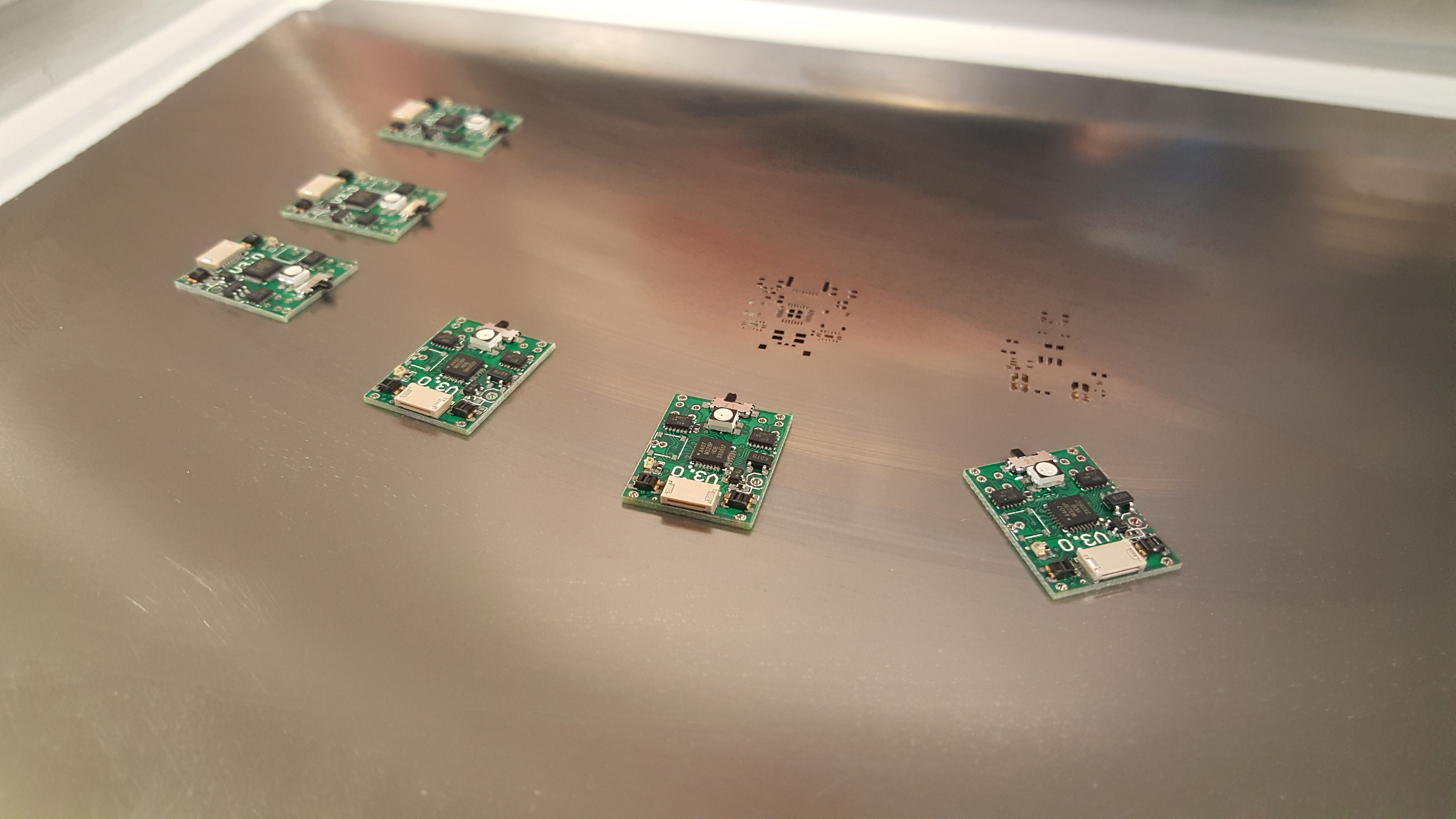
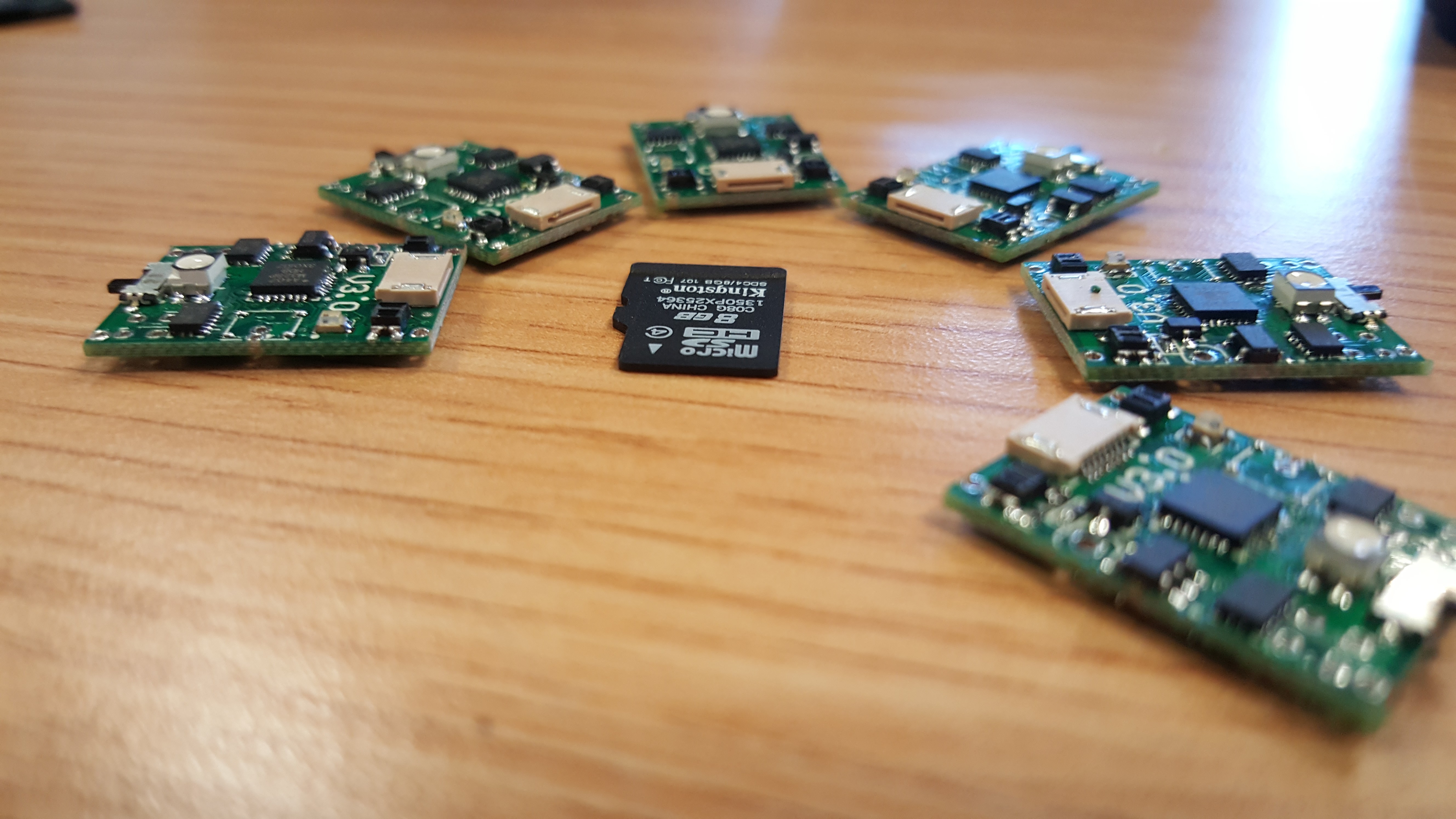
The bulk of the PCB work done.
Discussions
Become a Hackaday.io Member
Create an account to leave a comment. Already have an account? Log In.