 Capt. Flatus O'Flaherty ☠
License: Attribution-NonCommercial-ShareAlike 2.5 Generic (CC BY-NC-SA 2.5)

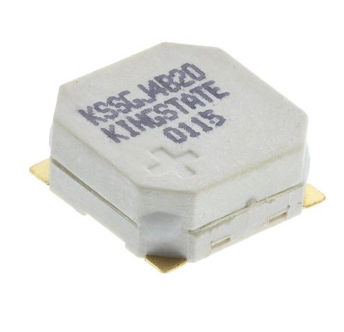
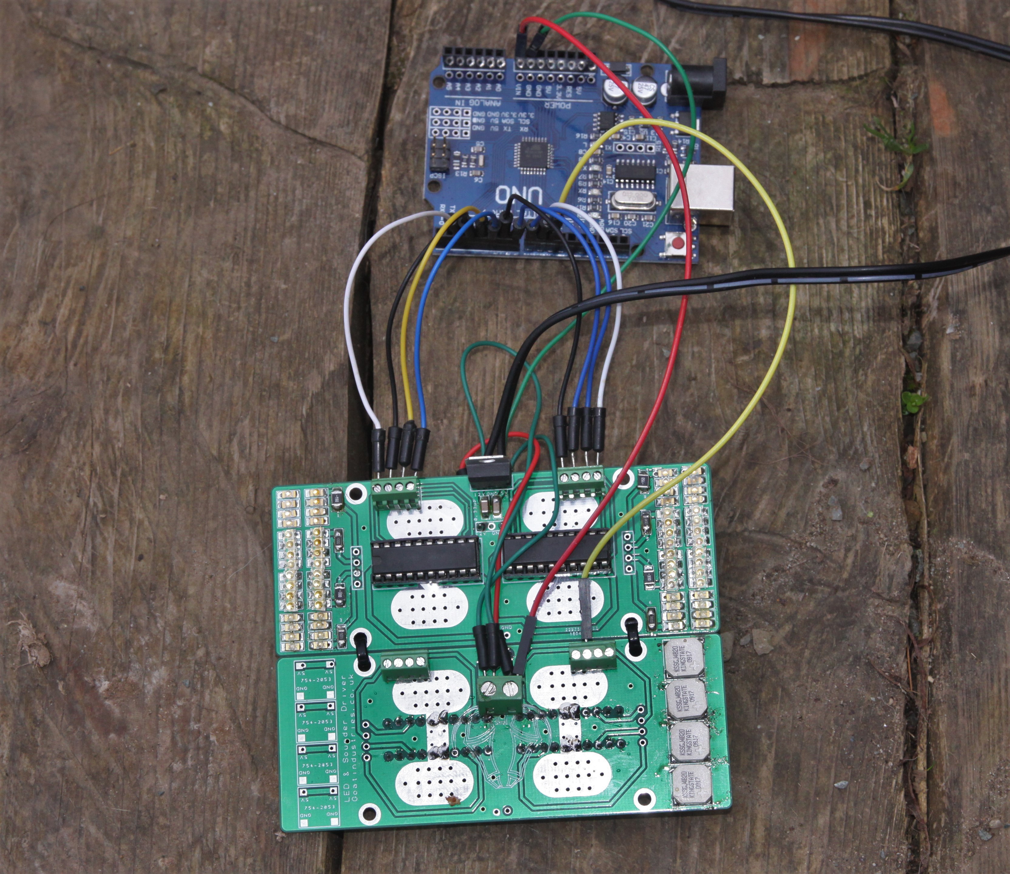
There are 8 available channels and on the front of the PCB are 8 banks of 8 1206 SMT LEDs and on the back are 8 surface mount 97 dB sounder / buzzers:
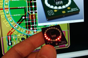
 Will the buzzers be able to compete with the noise of my 90 dB petrol motor? Will the LEDs be able to out shine the glare of the sun?
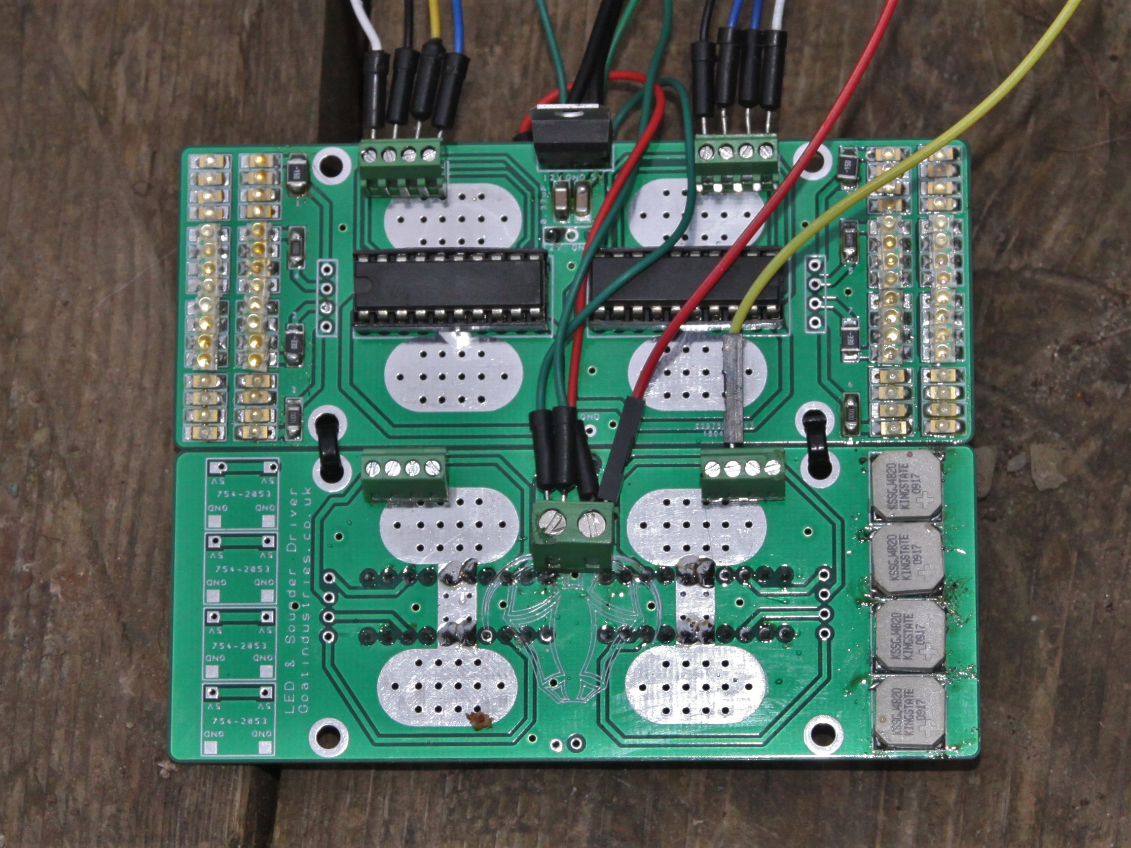
 Jens Hauke
 Erik Bosman
 FrazzledBadger
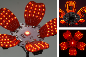
 potblitd