 body interaction team
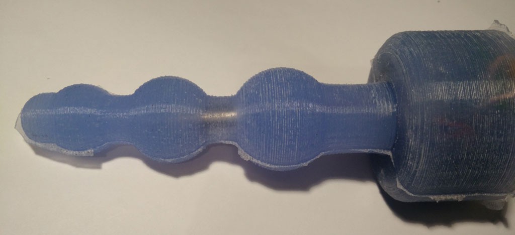
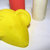
Building your own silicone molded vibrator becomes now easier. We already have presented 3d printed forms for building your personal vibrator (massage wand, wireless charged vibrator).
The pros are: the silicone case is safe and easy to clean and the vibrator case is flexible (compared to 3d printed sex toys).
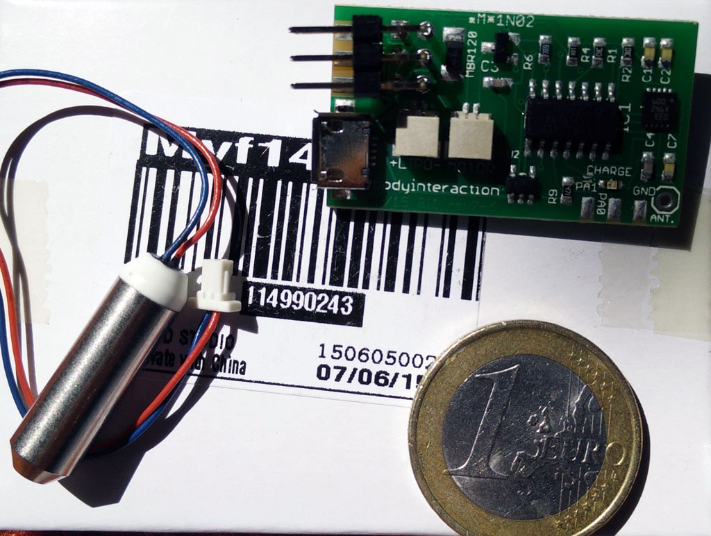

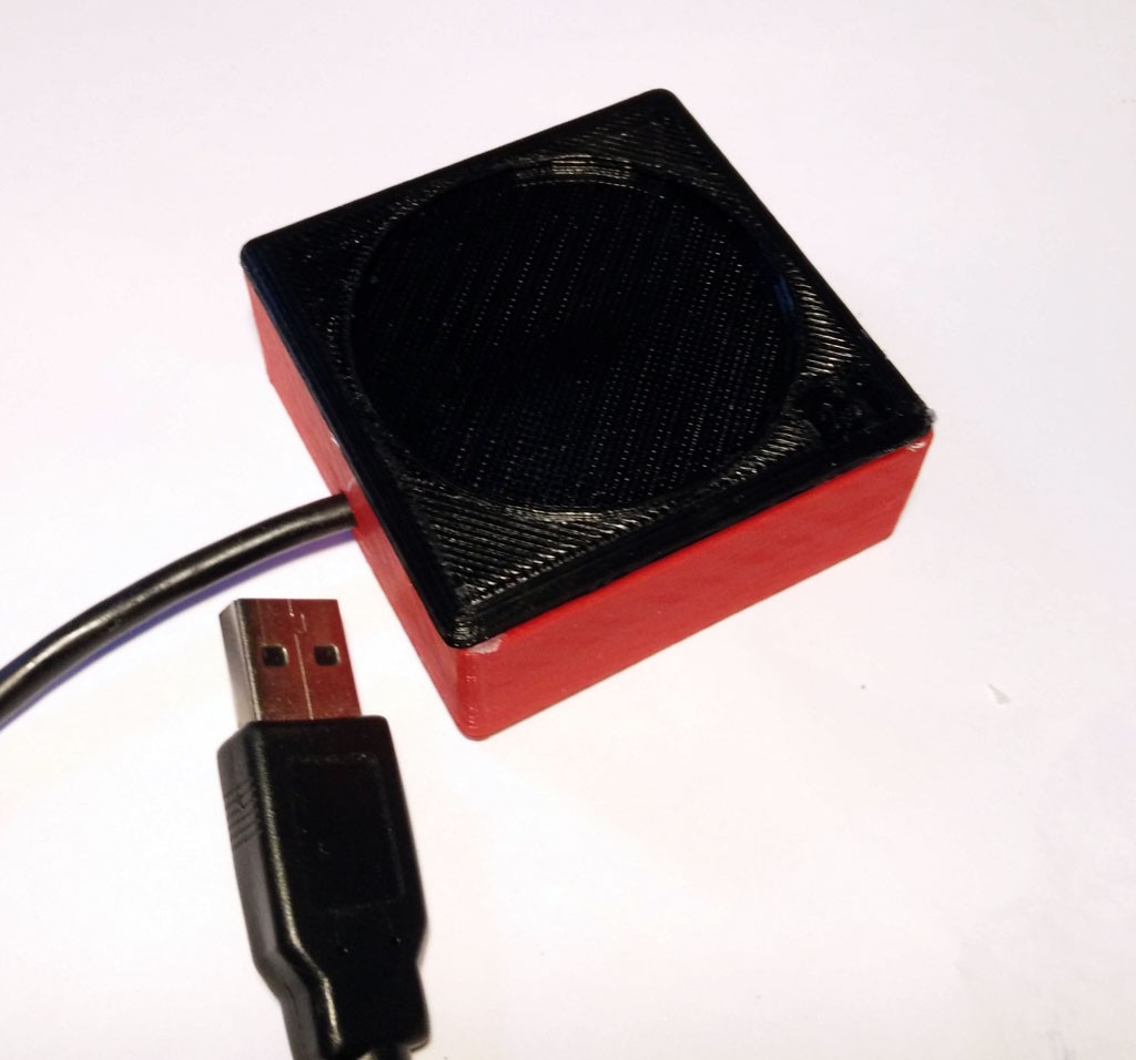
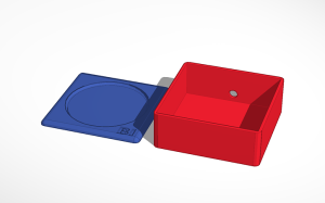
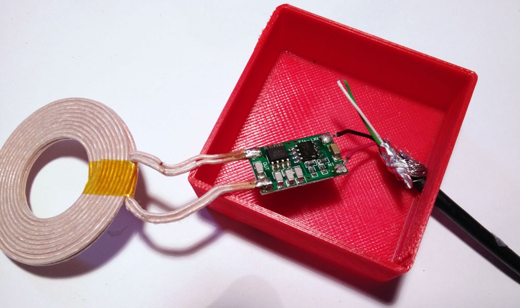
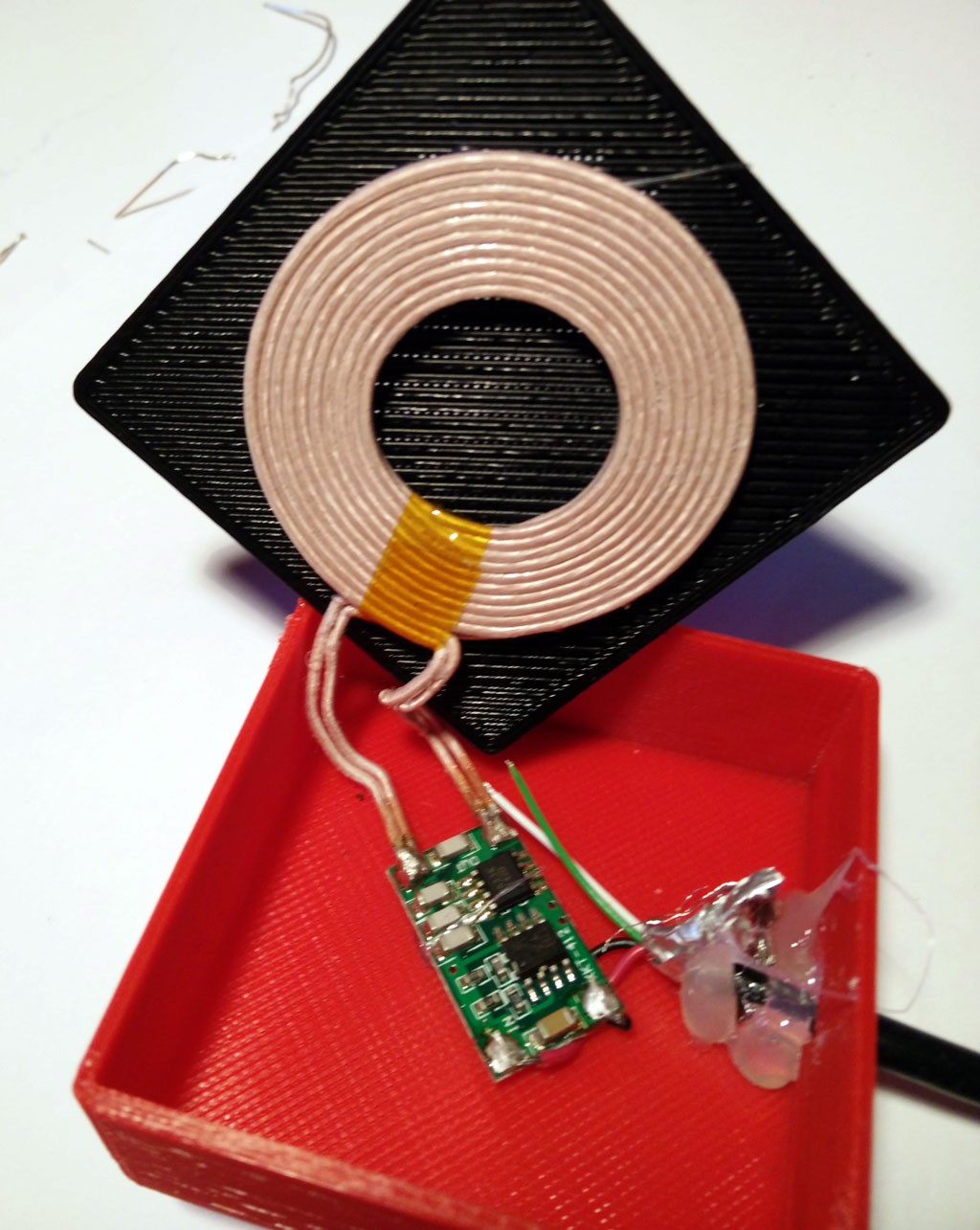
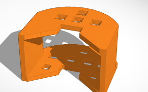
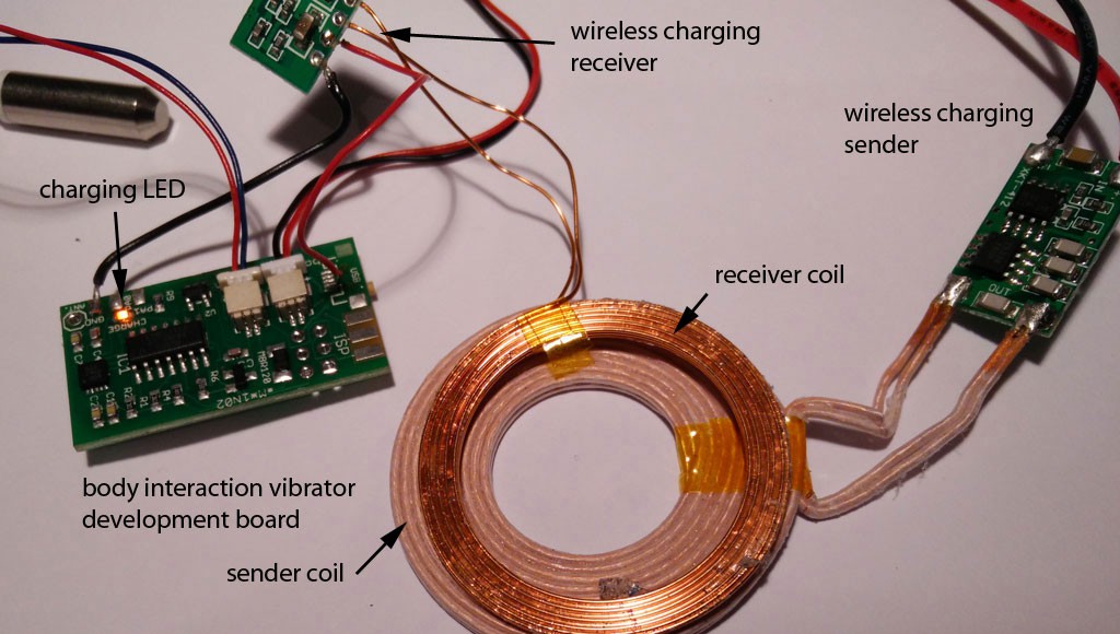
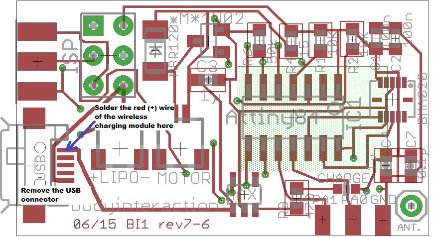
What is new? The electronics including battery are in the base of the vibrator. We developed a 3d printed enclosure for the electronics. This has several benefits: The assembling of the electronics and the molding itself is easier as everything is fixed within the enclosure. And it is more safe as the enclosure shields the electronics from the environment (and vice versa). In addition we used a different charging module from Seeed Studio. The input voltage is only 5V. Now you can connect the charging module with a USB connector and don’t need another power supply. (Look here for an explanation of wireless charging sender and receiver.)
heights. Just were you need the power.
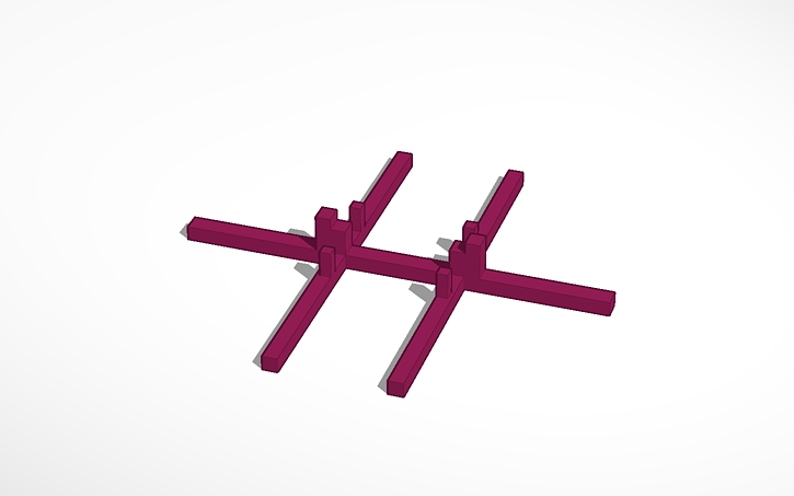
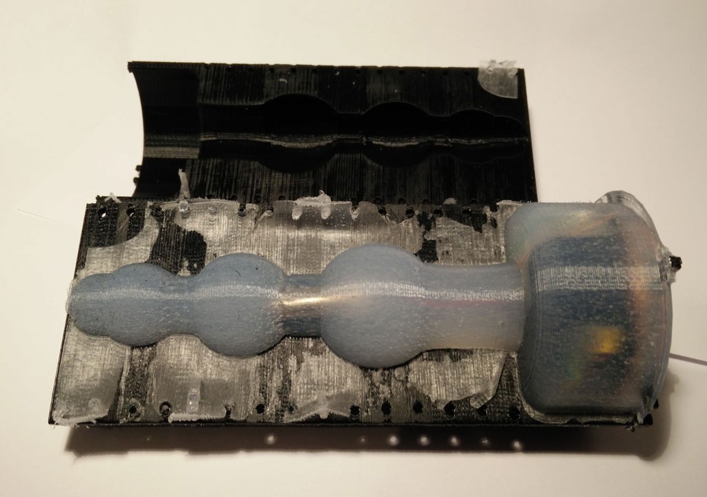
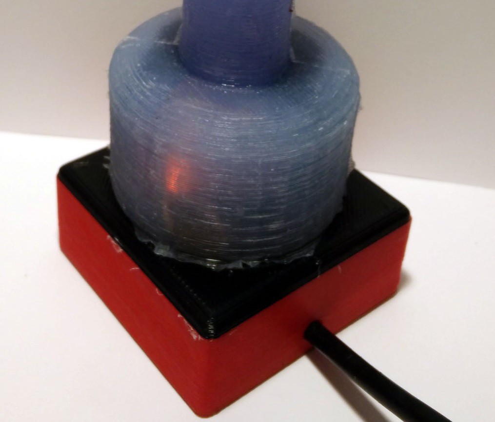
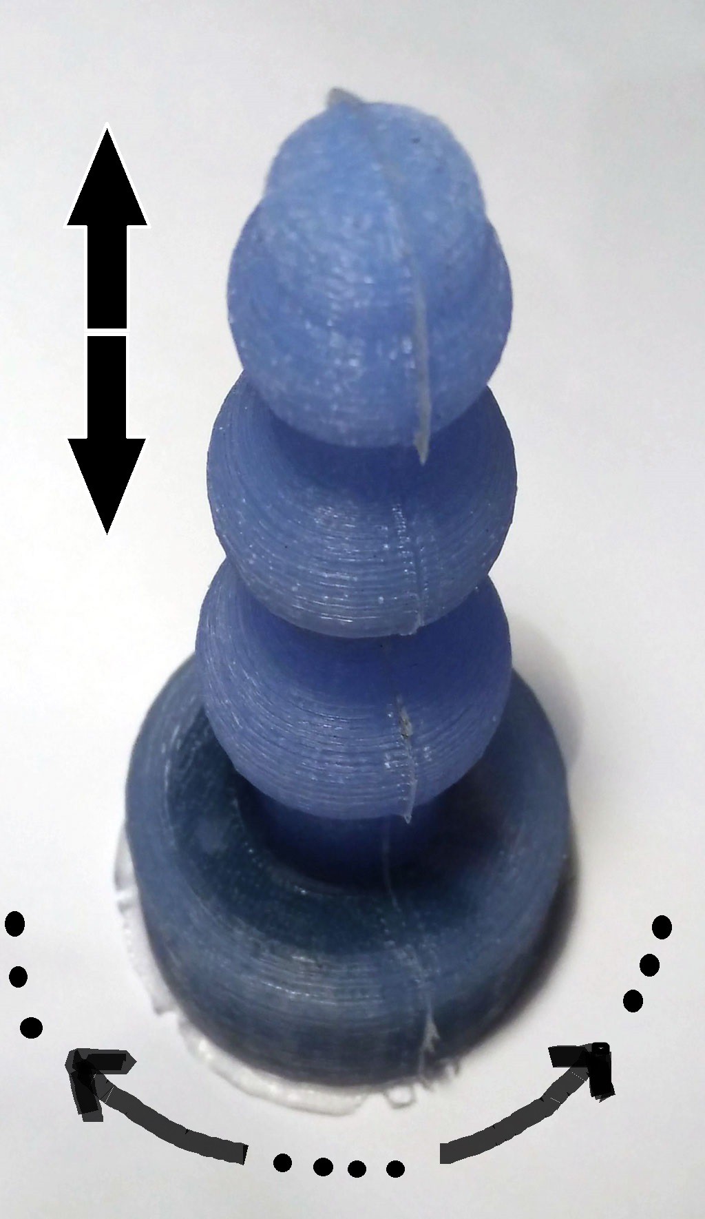
Finally the mounting is improved. The mounting holds the enclosure when it is inserted into the form.
 The mounting (together with the enclosure with the electronics)
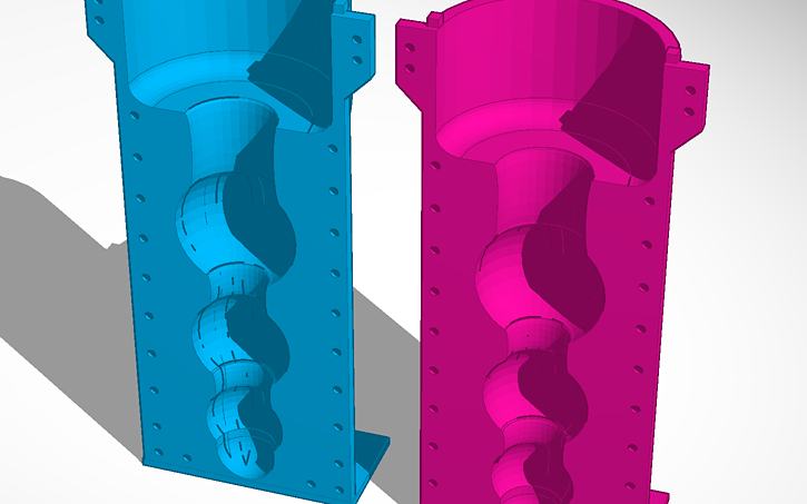
is inserted into the form. The form consists of two parts which must be
fastened together by tinker wire. It is a variation of the ball theme.
The mounting (together with the enclosure with the electronics)
is inserted into the form. The form consists of two parts which must be
fastened together by tinker wire. It is a variation of the ball theme.
 hanging:


 Brent Nelson
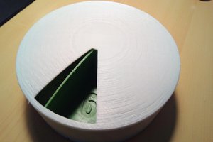
 Juan M. Casillas
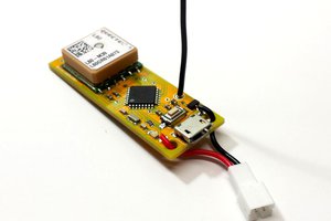
 nootropic design
 Chris K Cockrum
Jarrett, thank you very much for your comment. I will give it a try. Do you know if XTC 3D is safe when it is cured? I am worrying that chemicals in the XTC coating could "migrate" to the silicone.