 István Hegedűs
I am glad to report that the analog picture generation part of the drop-in TED replacement is ready!
The luminance signal is implemented with a look up table and a smart external circuit which is not a DAC so it generates perfect voltage levels for the various luminance signals (I don't want to release the circuit details at this point).
The chrominance signal was easier than I thought, however the DDS phase accumulator I had to increase to 24 bits because it turned out that the PAL standard requires very precise 4.433618 MHz frequency. Unfortunately I cannot test NTSC as I don't have an NTSC monitor but I am implementing that part too! I will leave that later for test users from US region.
To test the result I have created a PAL test screen top module which generates SMTPE bars and/or different color bars that I can change in code. The FPGA board I have hooked up to a C16 motherboard via TED chip socket's Sync and Color pins in order to see the real composite output on my monitor. The result pictures speak for themselves.
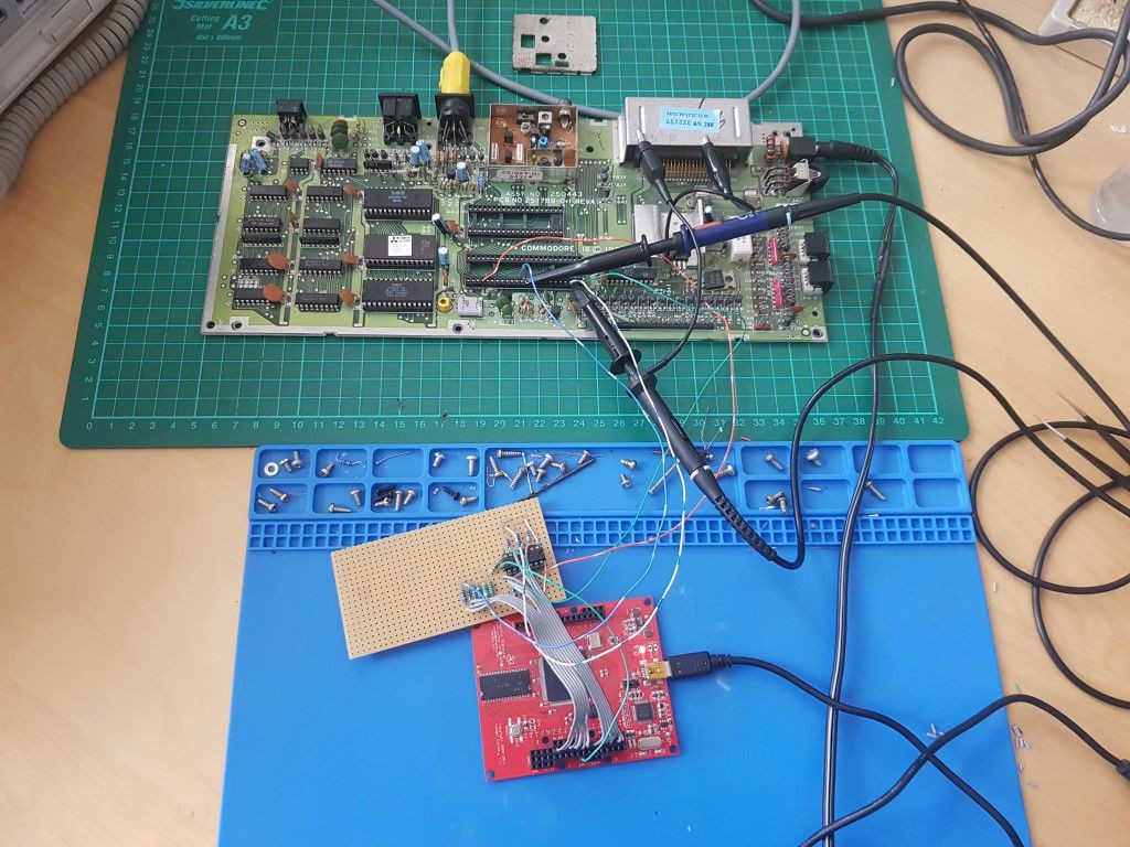
This is my testbench using a Papilio Pro board and some analog components on the test board.
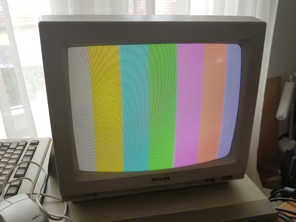
SMTPE color bars generated via the FPGA and C16 RF modulator.
(those moisters are visible only on the photo, but in real life they are not visible)
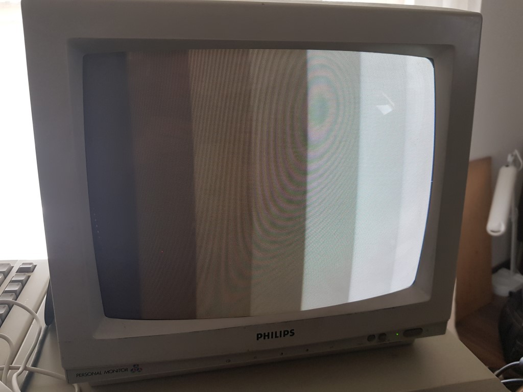
Testing luminance levels with white color (grayscale).
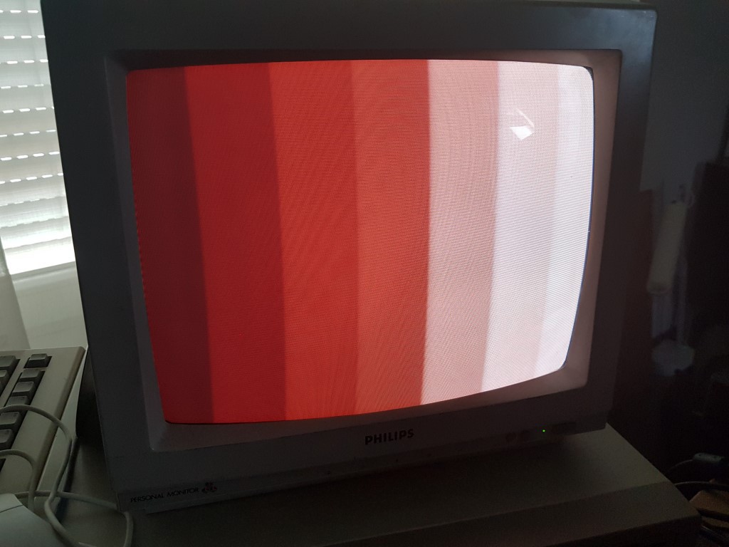
Same luminance test with red color bars.
Next step is to start to design the PCB! It will take some time as I have never designed a 4 layers PCB with BGA chip on it. Current FPGA choice is Spartan 6 LX4 or LX9. My goal is to keep cost as low as possible to create a competitive chip in price.
Discussions
Become a Hackaday.io Member
Create an account to leave a comment. Already have an account? Log In.