Our hands are quite the feat of engineering as they can maximize flexibility and strength at the same time with regards to their fibrous, flexible muscle structure. And as most of the tools used in daily life and industrial work are designed to be used by humans, the already built system is a perfect working ground for human hands. But due to the vulnerability of human flesh to hazardous materials and pointy things, there are jobs that are ought to be done by an inhuman structure - such as lifting a pile of rocks or closing shutting down nuclear reactors that went through a nuclear core meltdown.
Several robotics research groups across the globe are working to create the ultimate inhuman structure – also widely known as robots – in order to minimize the risk, the robots can easily take for a human. But due to aforementioned already built system being built around the general design of a human hand, they have to design their robots with regards to this premise. And this situation leads to grippers not being flexible or strong enough for the purpose, by favoring one gripper type over the other as materials such as aluminum or plastic, which doesnt have the attributes the human flesh has. Most researchers use a three fingered gripper design as a hybrid of a human hand and an industrial two-fingered gripper design. This results in the design being moderate in both flexibility and strength.
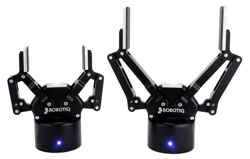
Two fingered gripper design, mostly used in industrial workspaces (Credit: Robotiq)
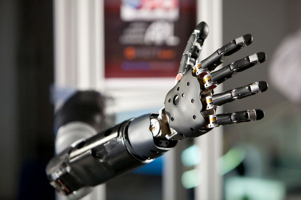
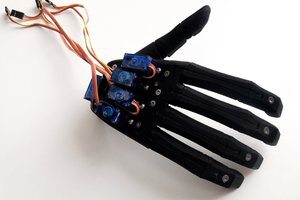
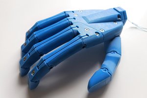
Bionic hand, used in prosthesises and experimental search and resque robots (Credit: DARPA)
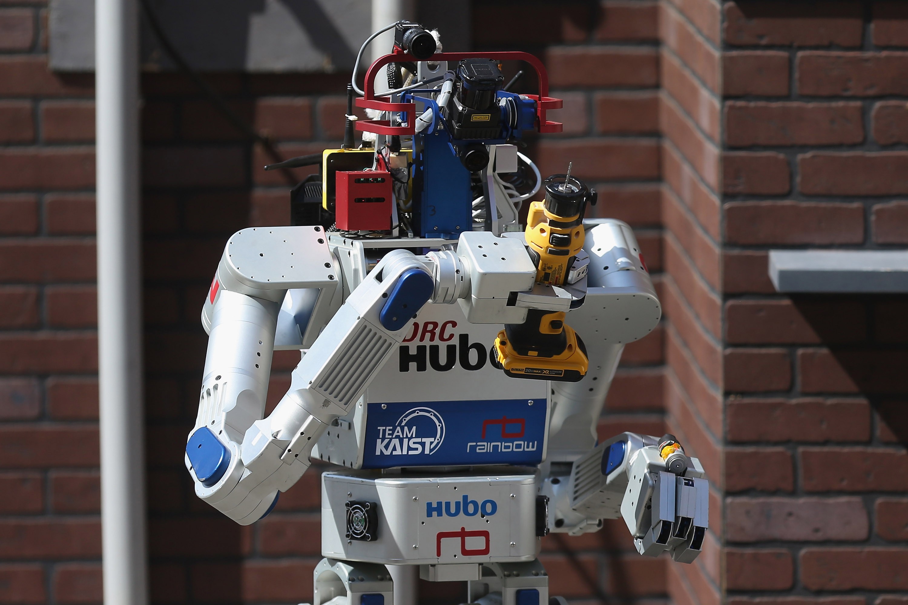
DRC-HUBO of Team KAIST, winner of the 2015 DARPA Robotics Challange
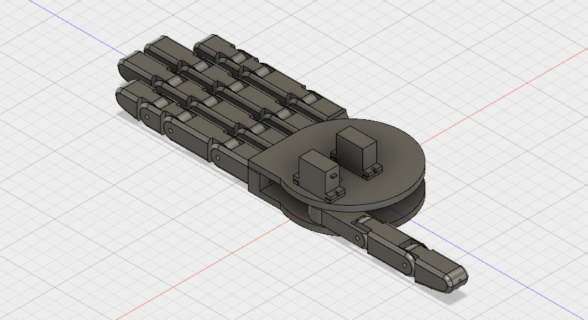
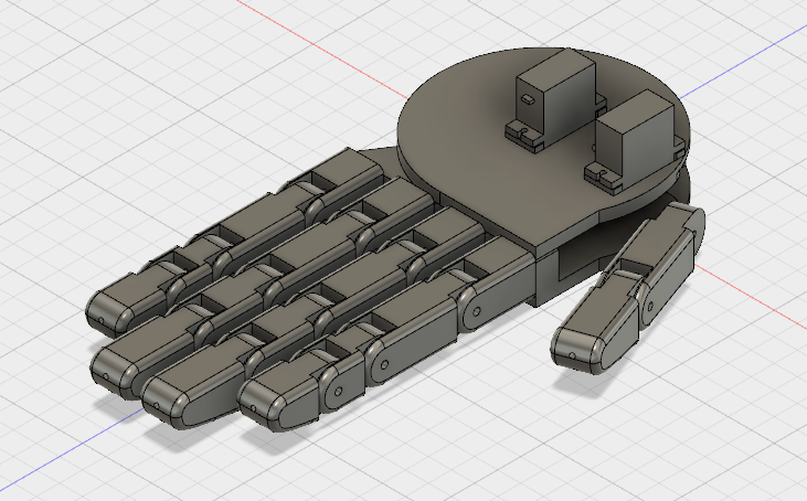
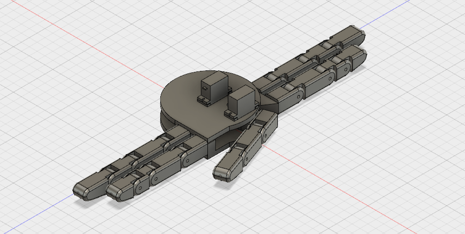
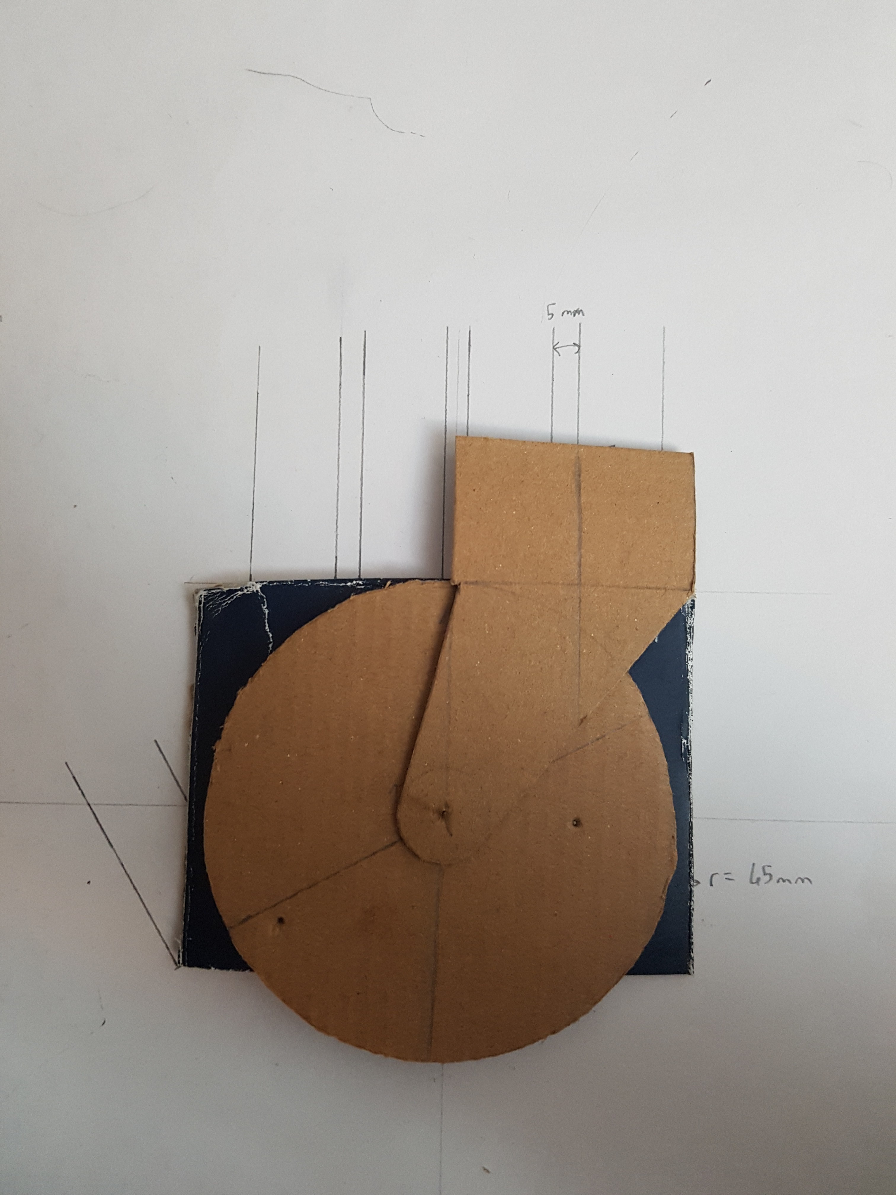
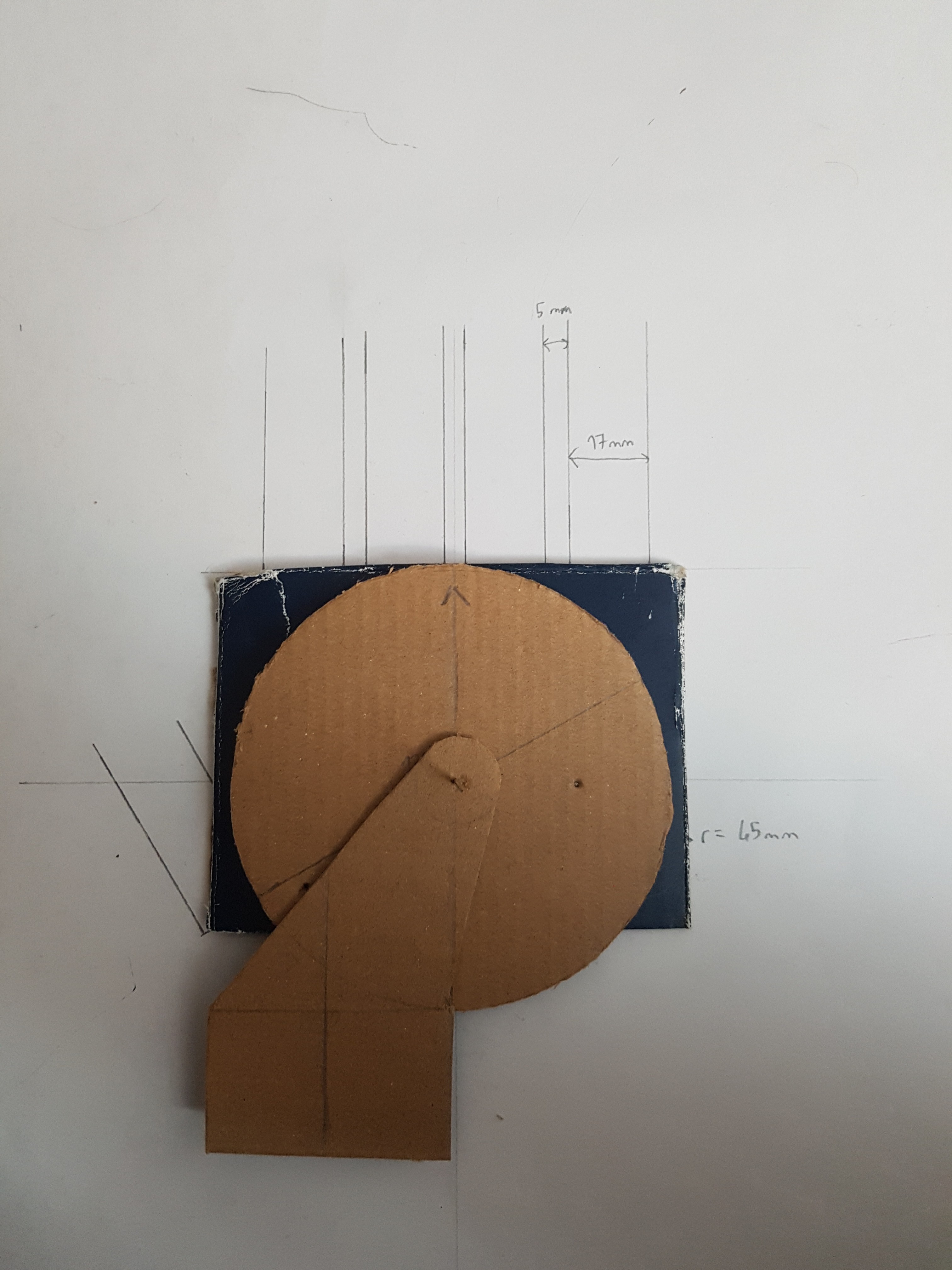
As seen in the picture above, the hybrid three fingered grippers have to work around the tools that are designed by humans, for humans. This results with robots having to do complicated movements to hold a tool with a grip which is ultimately unnatural. With the use of Robotic Hand With Interchangable Gripper Types (RHIG), robots and teams can tackle the task at hand with a more natural approach as their designs can mimic human movements better.
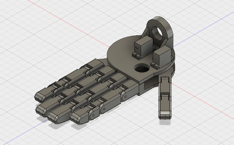
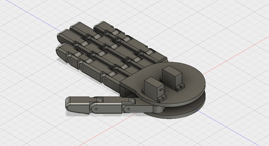
All the parts – excluding the servos, screws and the bowden cables – can be printed on a desktop 3D printer, making RHIG easy to produce. And as the only extra parts that differentiate this project from a bionic hand is only two servo motors, RHIG is also cheap to produce.
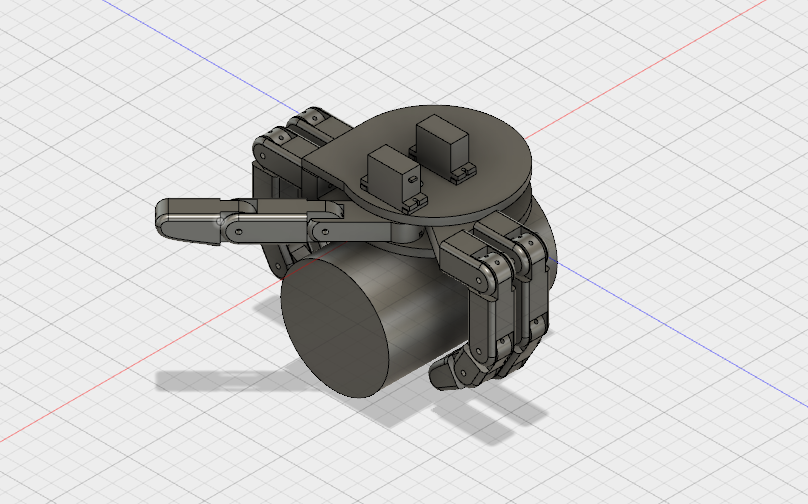
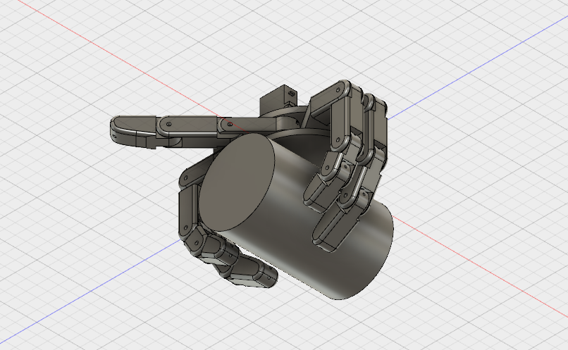
The usage of the the better grip mode can be seen in the screenshots of the 3D design file above. In order to improve upon this design the finger lengths can be adjusted. And also, the thumb can be implemented in this mode as well to use it as a three finger gripper.
Due to not having access to a 3D printer, a physical first prototype will not be made for the time being. Although as the 3D design files will be accessible, if you have the tools required, you are welcomed to make one for yourself!
 Supercell
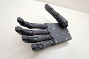
 Jason Bender