 Swaleh Owais
I have constructed the general frame of the conveyor belt.
I am using aluminum to keep the system light. Additionally, a metal structure will be significantly more robust than a laser cut wood system.
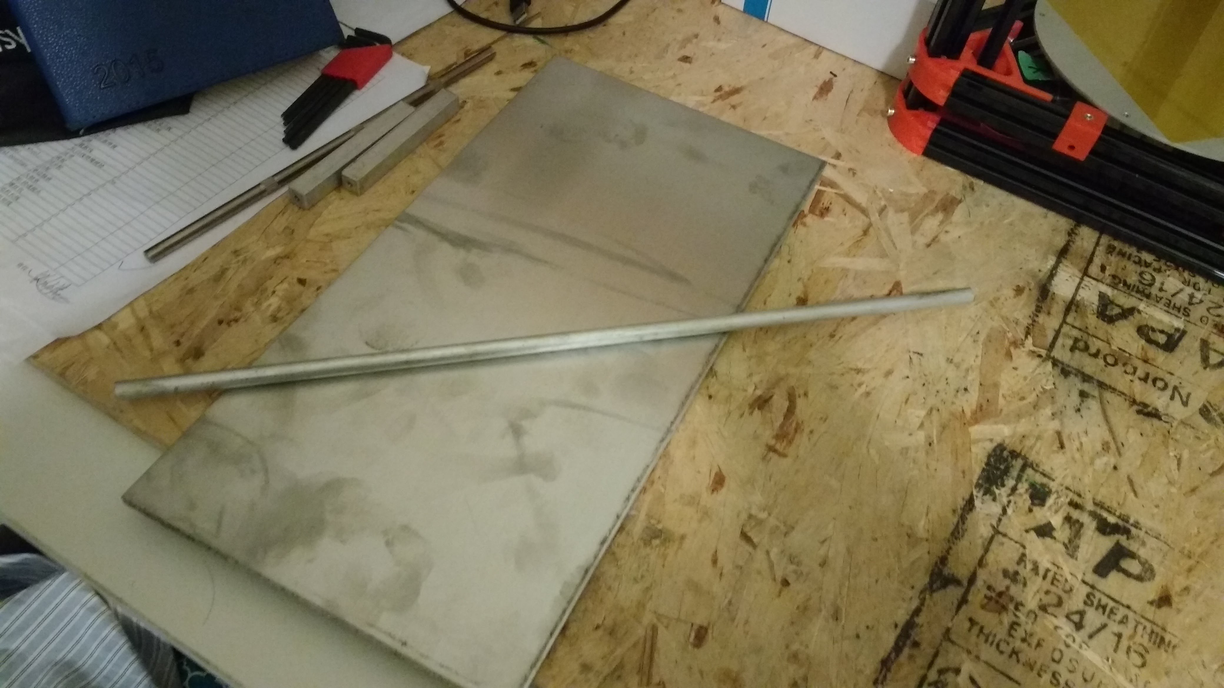
[Figure 1: 6061 Aluminum Plate, Round Stock, and Square Stock]
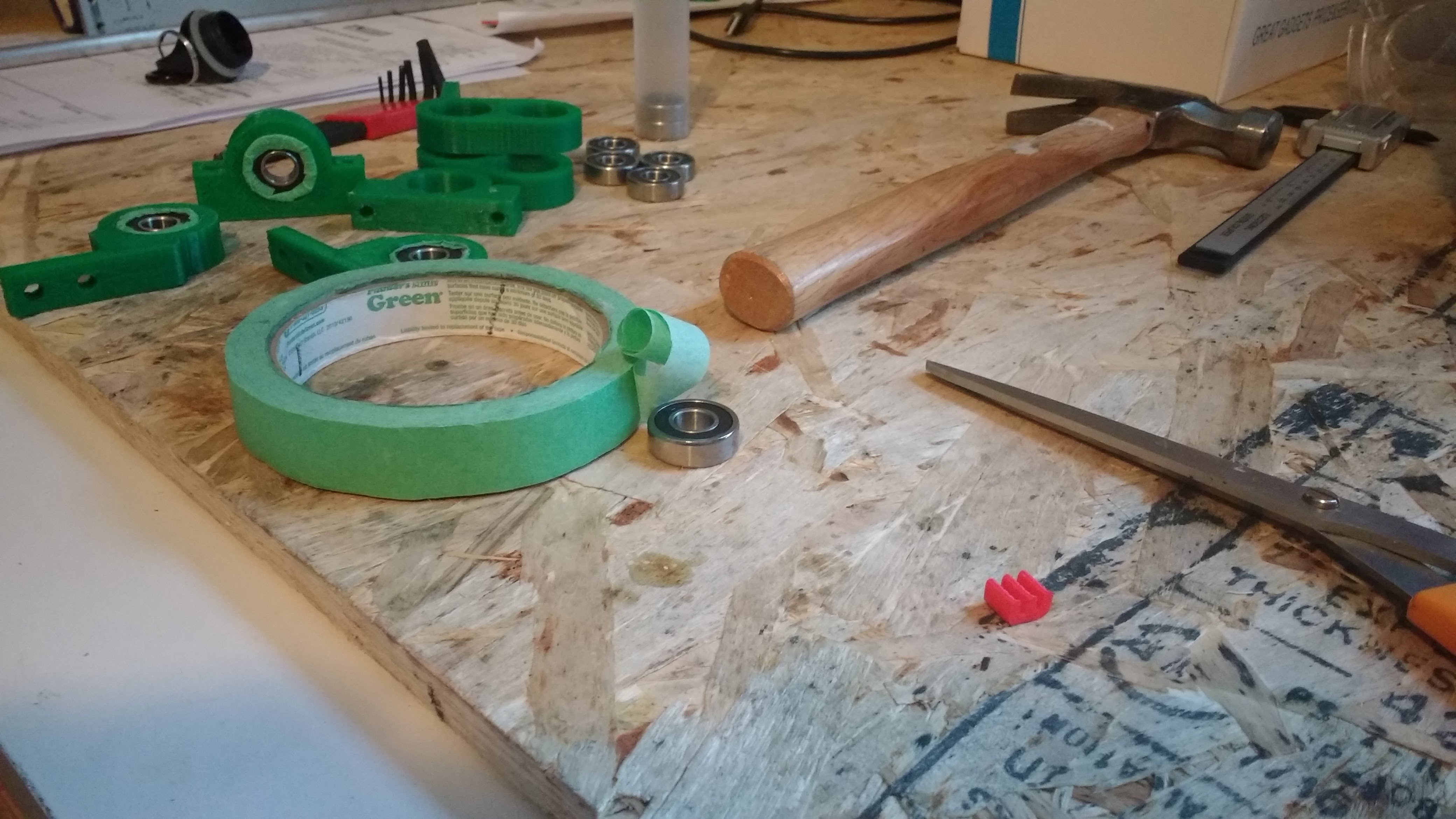
Each of the rollers will be supported by a ball bearings. I have printed bearing housings that mount onto the plate. I thought the bearings would be 0.875 in diameter. This was not the case. Some painter's tape crudely solved the problem.

[Figure 2: Ball Bearings for Rollers]
[Figure 3: 3D Printed Bearing Housing]

[Figure 4: Finding out Ball Bearing isn't 7/8]
[Figure 5: Increasing OD of Ball Bearing]
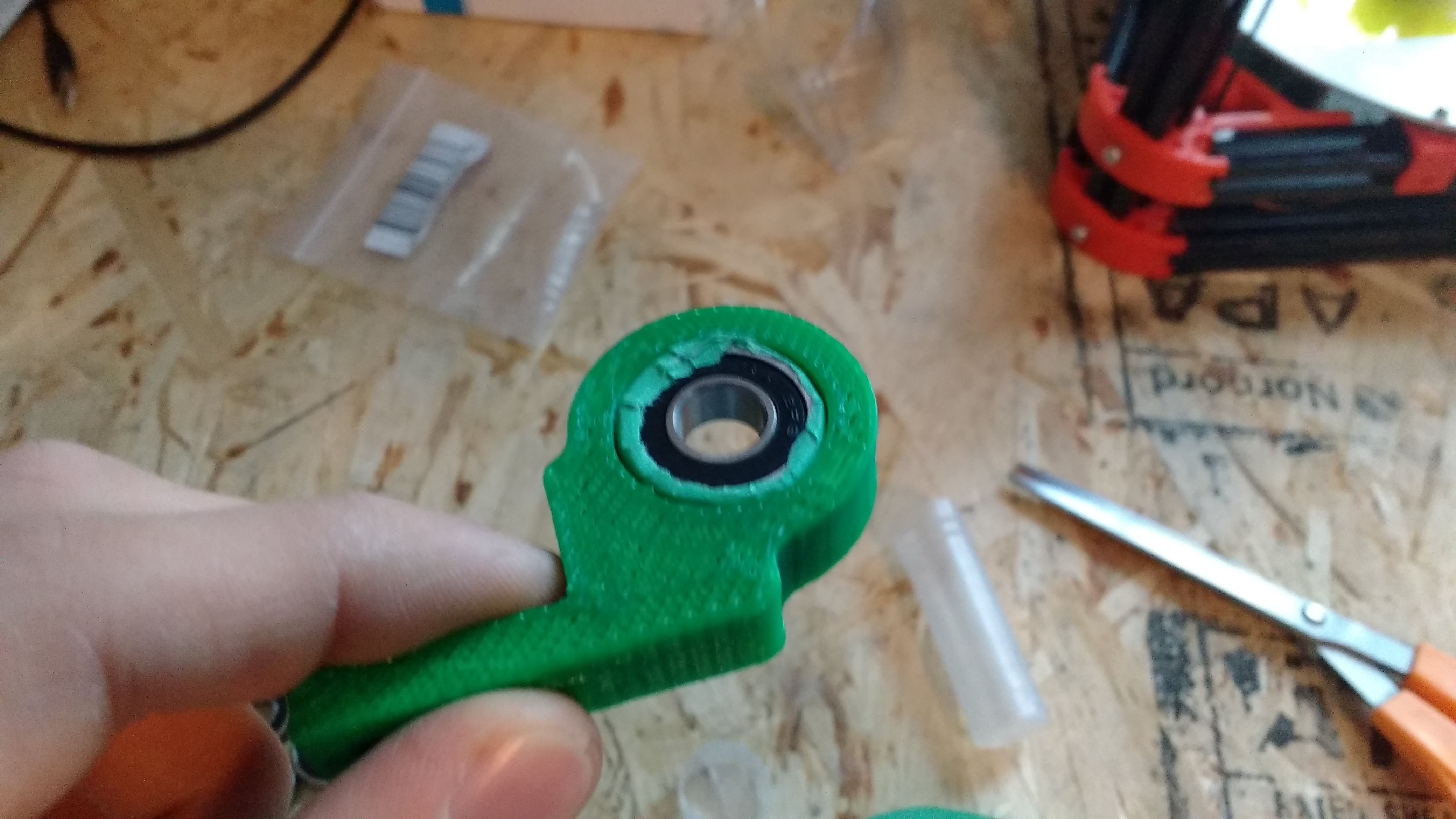
[Figure 6: Inserting Ball Bearing into Housing]
The idle rollers are simple 3/8 rods. To increase traction, the motorize roller is wrapped with high friction material. Additionally, a 3D Printed adapter increases the diameter of the roller and resultingly the contact area with the belt. Originally, the roller was wrapped with a rubber mat but this material was replaced with electrical tape. The metal has tapped holes for the bearing housings.
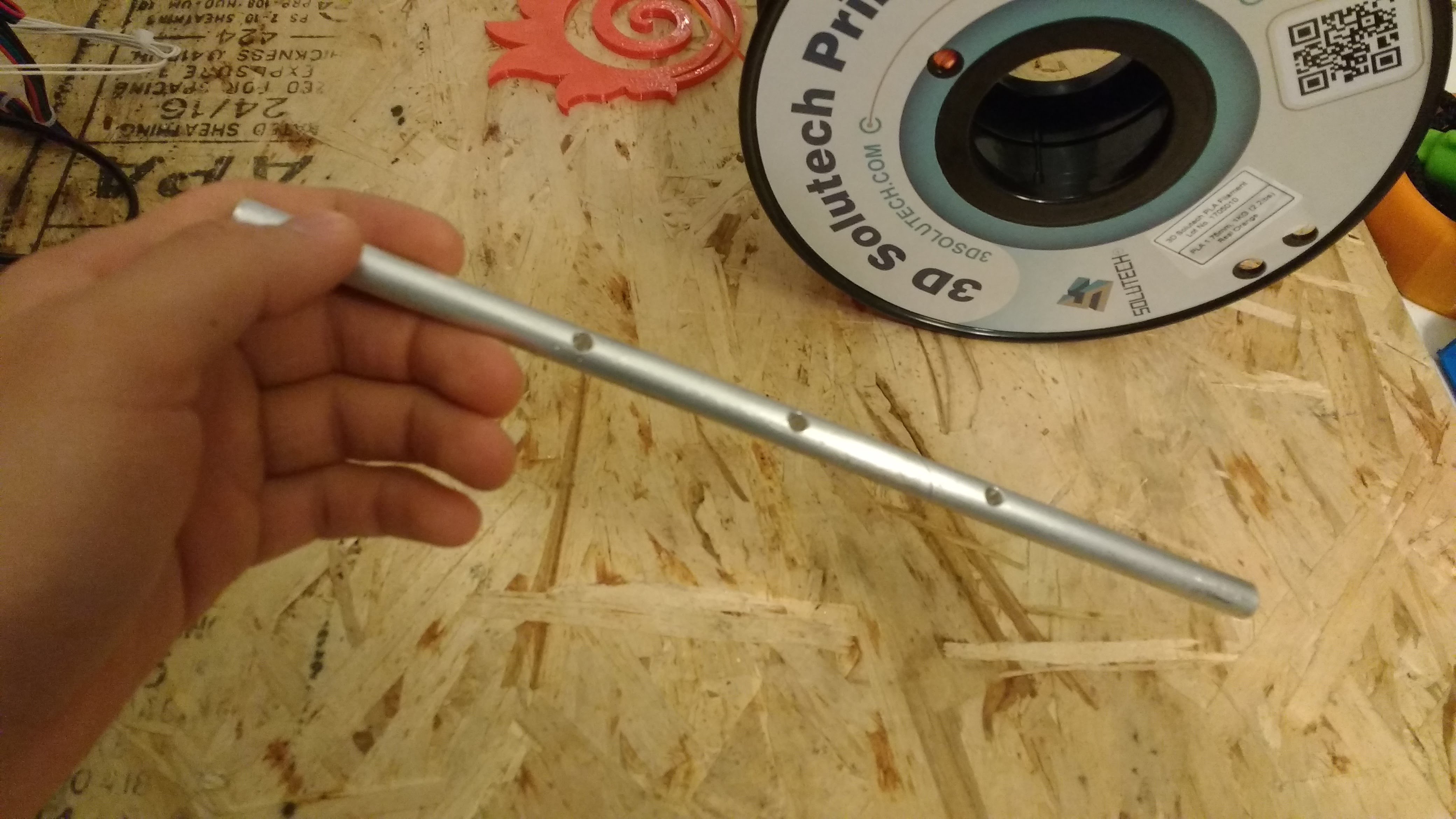
[Figure 7: Adding Mounting Holes to Axle for 3D Printed Adapter]
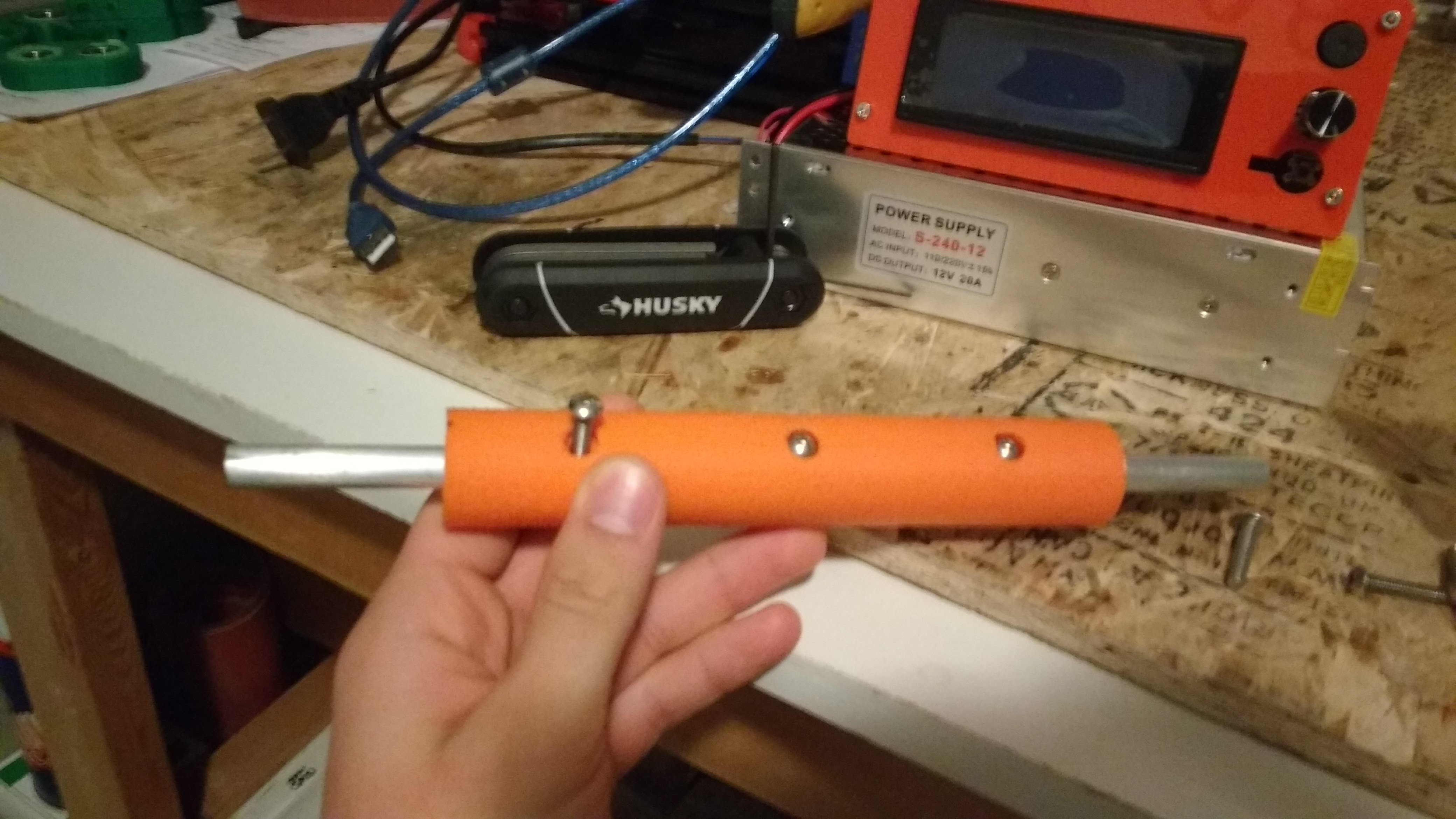
[Figure 8: Mounting 3D Printed Adapter]
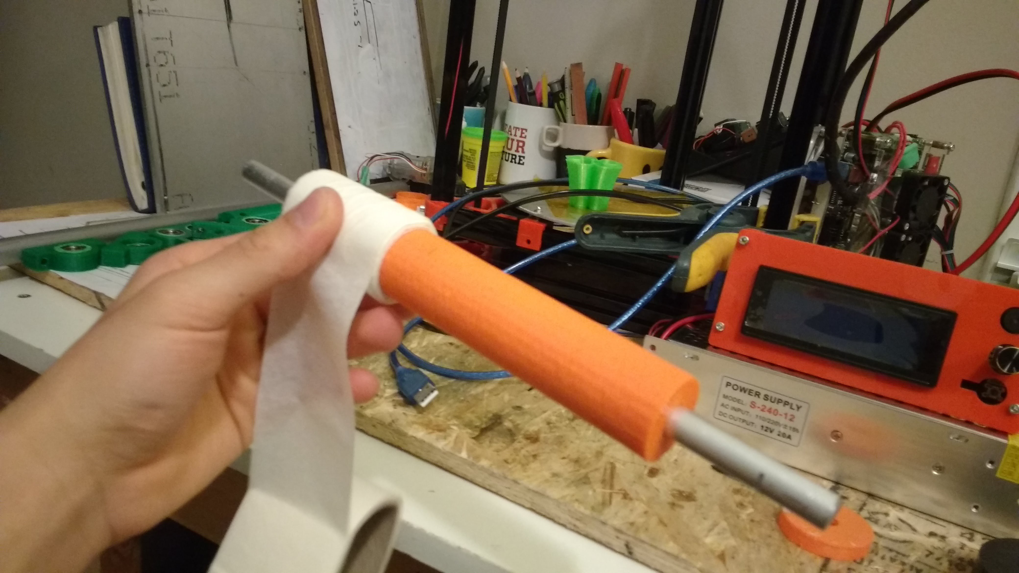
[Figure 9: Increase OD with Masking Tape]
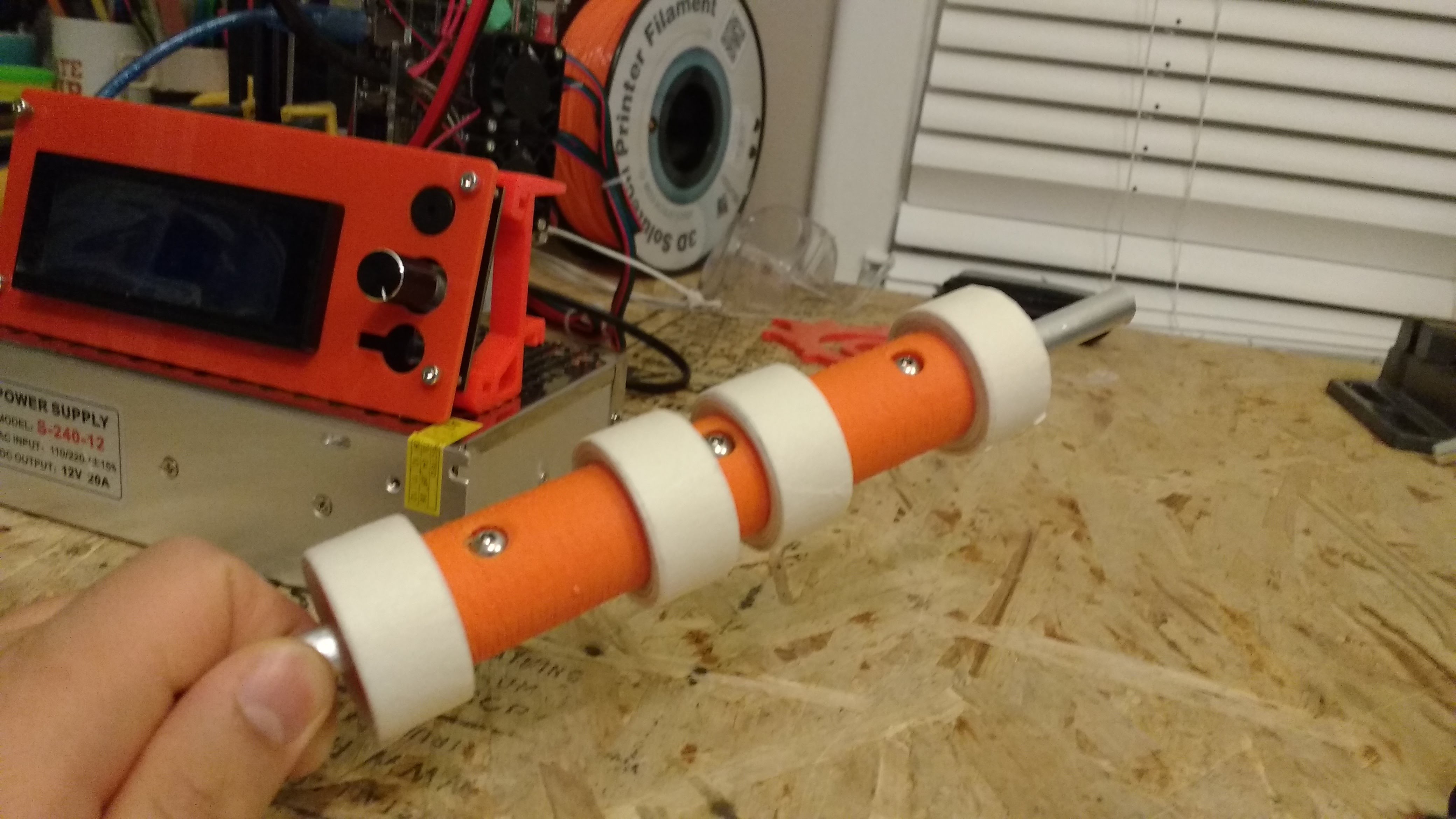
[Figure 10: Roller Wrapped with Masking Tape]
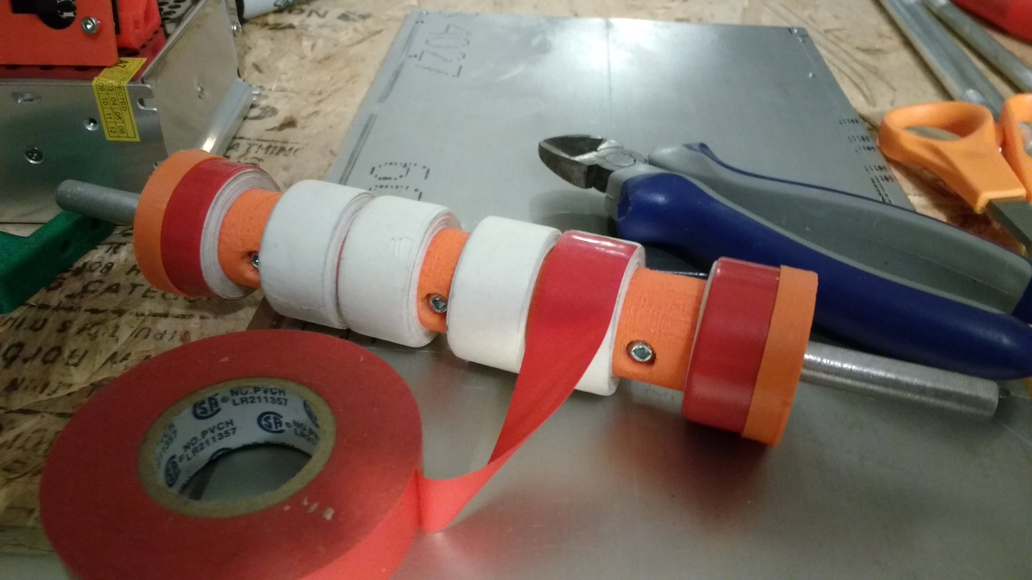
[Figure 11: Wrapping roller with Electrical Tape]
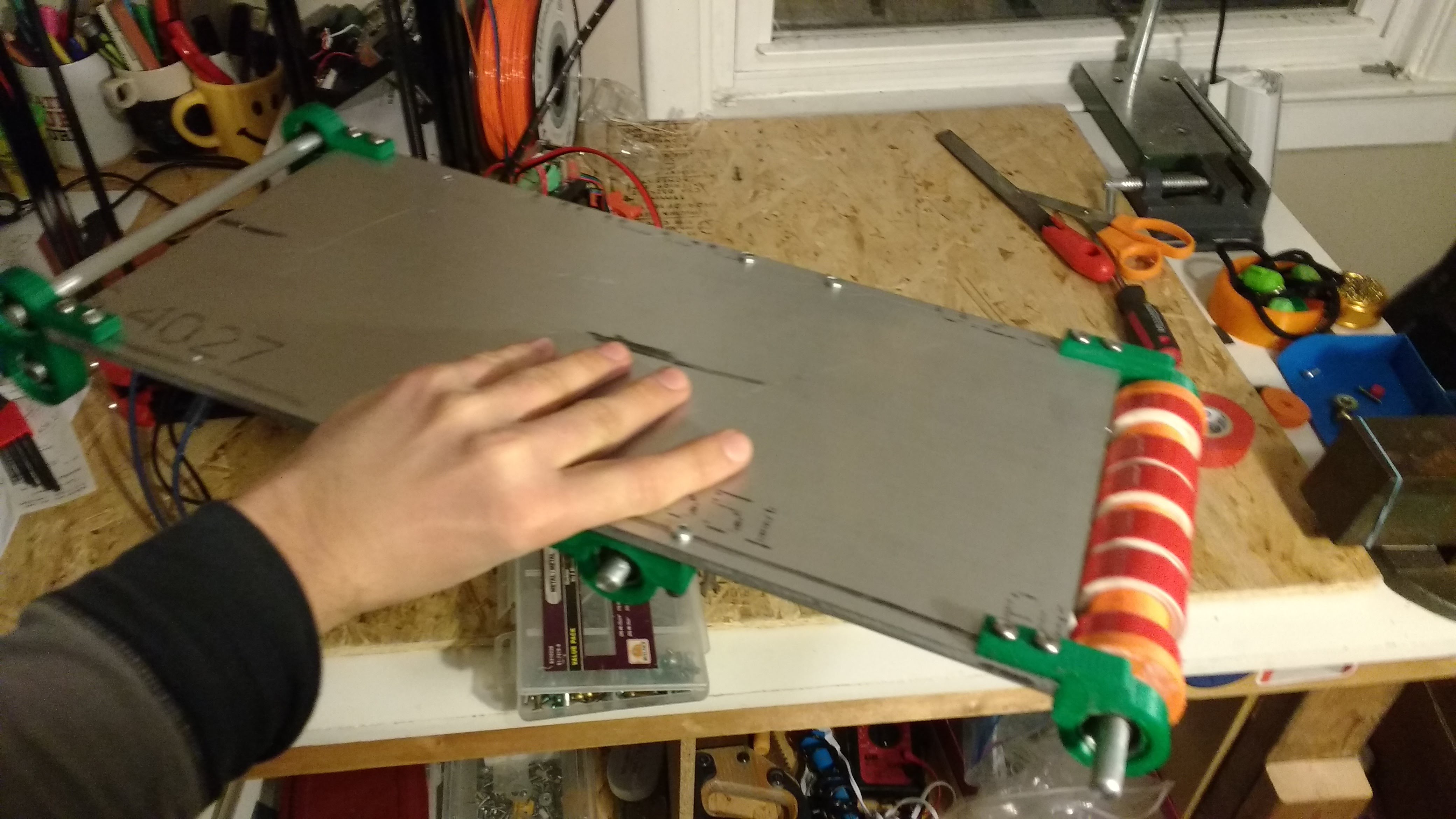
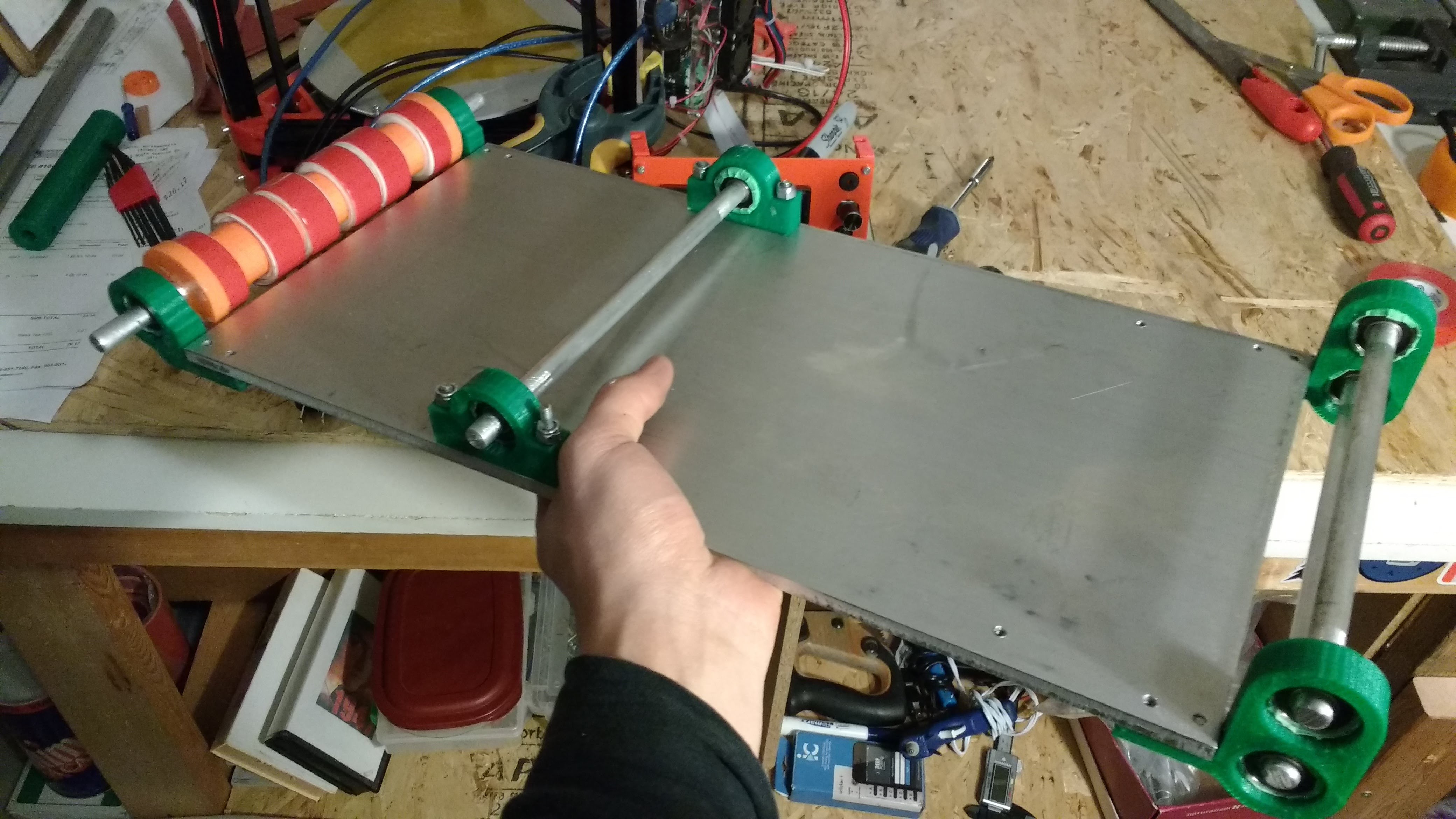
[Figure 12, 13: Rollers Mounted on Plate]
The heating bed was mounted to the metal plate. Clearance holes were cut for the heating bed cables. Plastic spacers were placed beneath the heating bed to ensure the entire bed does not turn into a heat sink.

[Figure 14: Adding Clearance Holes to Plate for Heat Bed]
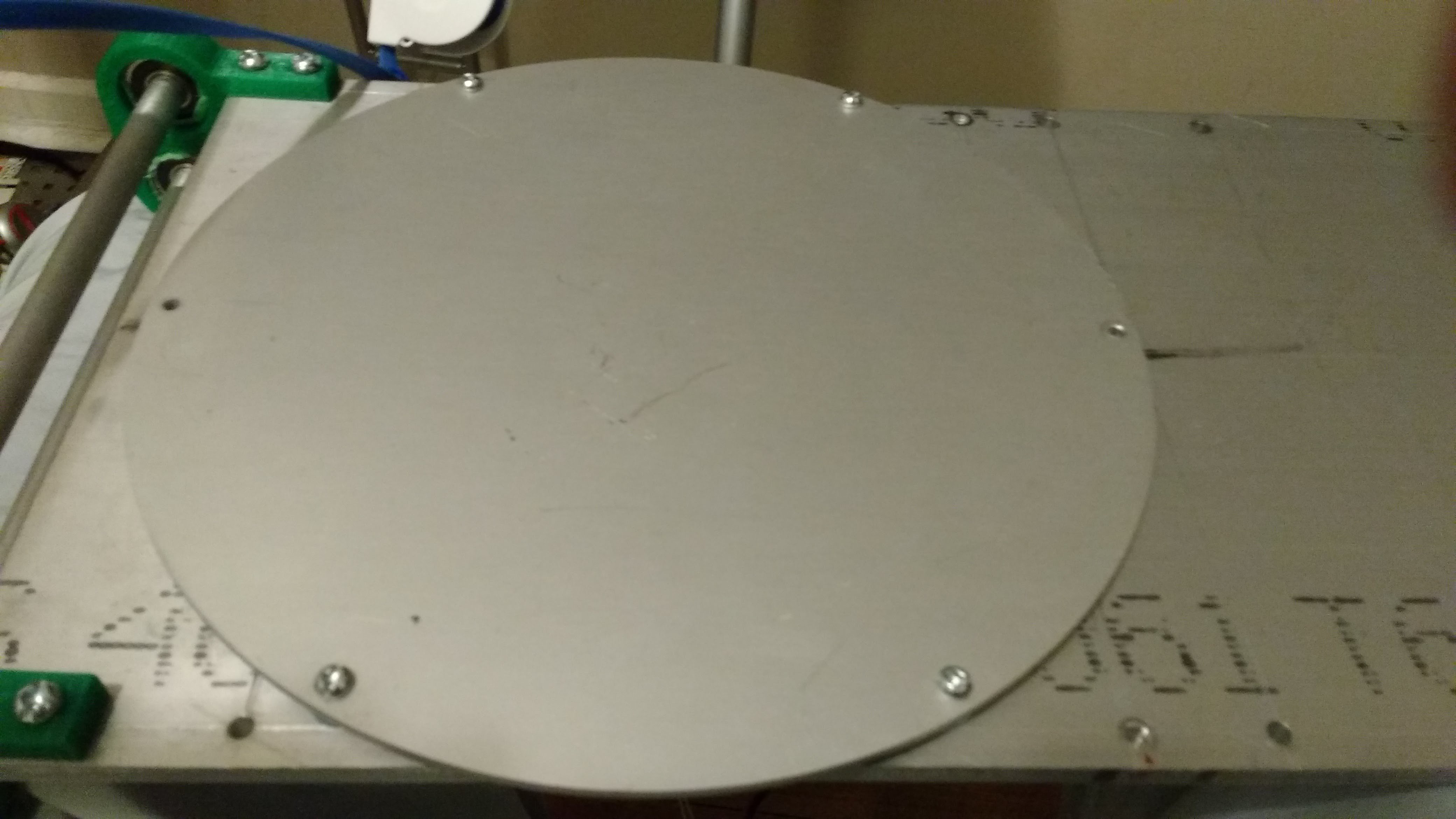
[Figure 15: Mounting Heating Bed to Plate]
I built the belt, last since I knew it would be the most irksome component. I make the belt by connecting two ends of a steel shim with Kapton tape. Since the shim has a small thickness of 1 thou., it conforms nicely to the shape of the rollers. I tensioned the belt by lowering the middle roller with spacers. I wrapped the belt with Painter's Tape to provide a nice printing surface for the print head. I printed simple mounts to connect the Delta 3D printer to the print bed and machined metal stands for the front of the conveyor.
[Figure 16: Connecting Shim with Kapton Tape]

[Figure 17: Apply Painter's Tape to Belt]
[Figure 18: 3D Printed Mounts for Conveyor Belt]
[Figure 19: Metal Stand for Conveyor]
I plan on running a dry test before I motorize the front roller. I will print a part on the conveyor belt and then manually rotate the front roller. I will investigate the effectiveness of the belt in ejecting the part.
Discussions
Become a Hackaday.io Member
Create an account to leave a comment. Already have an account? Log In.