 Dennis
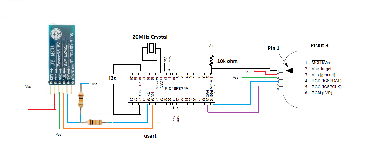
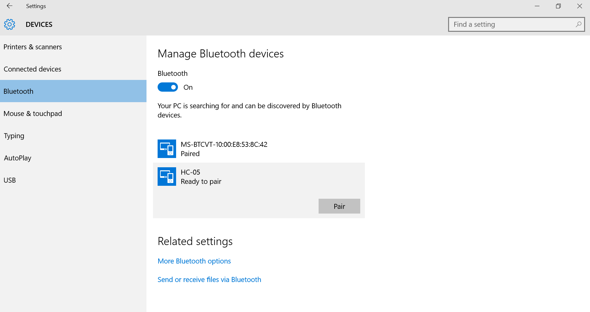
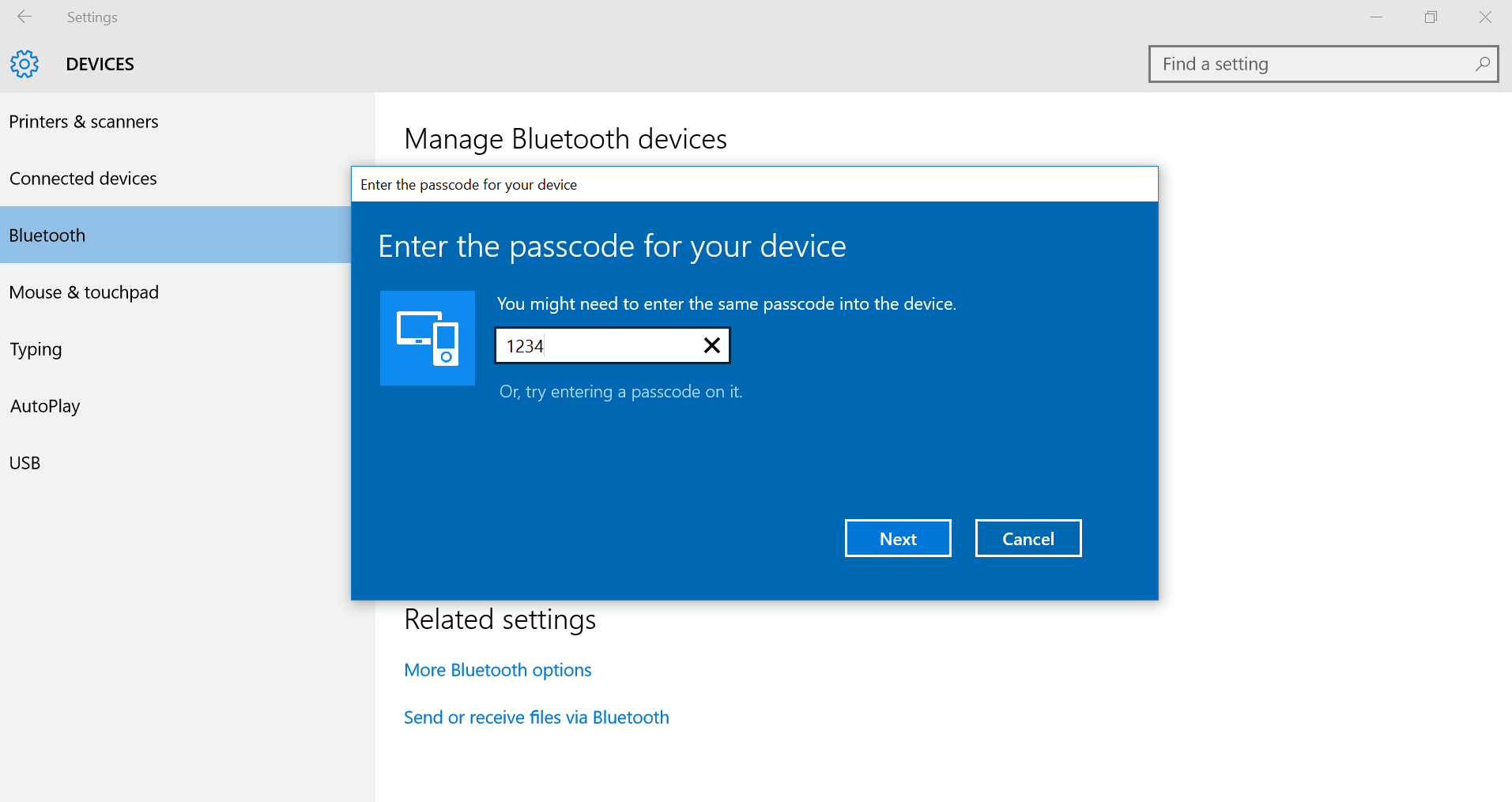
To make Squid as flexible as possible, the Squid will have three interface options to receive commands from an external controller. The options are Bluetooth, I2C and a serial port. Commands will be simple, such as “m1f” meaning motor 1 forward. A configuration page can be accessed via Bluetooth to configure Squid’s motor ports and I/O ports. The Squid can also be run in a standalone mode to allow users to control a bot without an external controller. Users will be able to directly program Squid’s PICs via ICSP (In Circuit Serial Ports) using “C”. Squid has 16 h-bridges that can individually drive small DC motors (800mA per channel) or two h-bridges can be combined to drive a Step motor. In addition, 16 I/O ports can be configured as analog inputs (default) or as digital inputs or digital outputs.
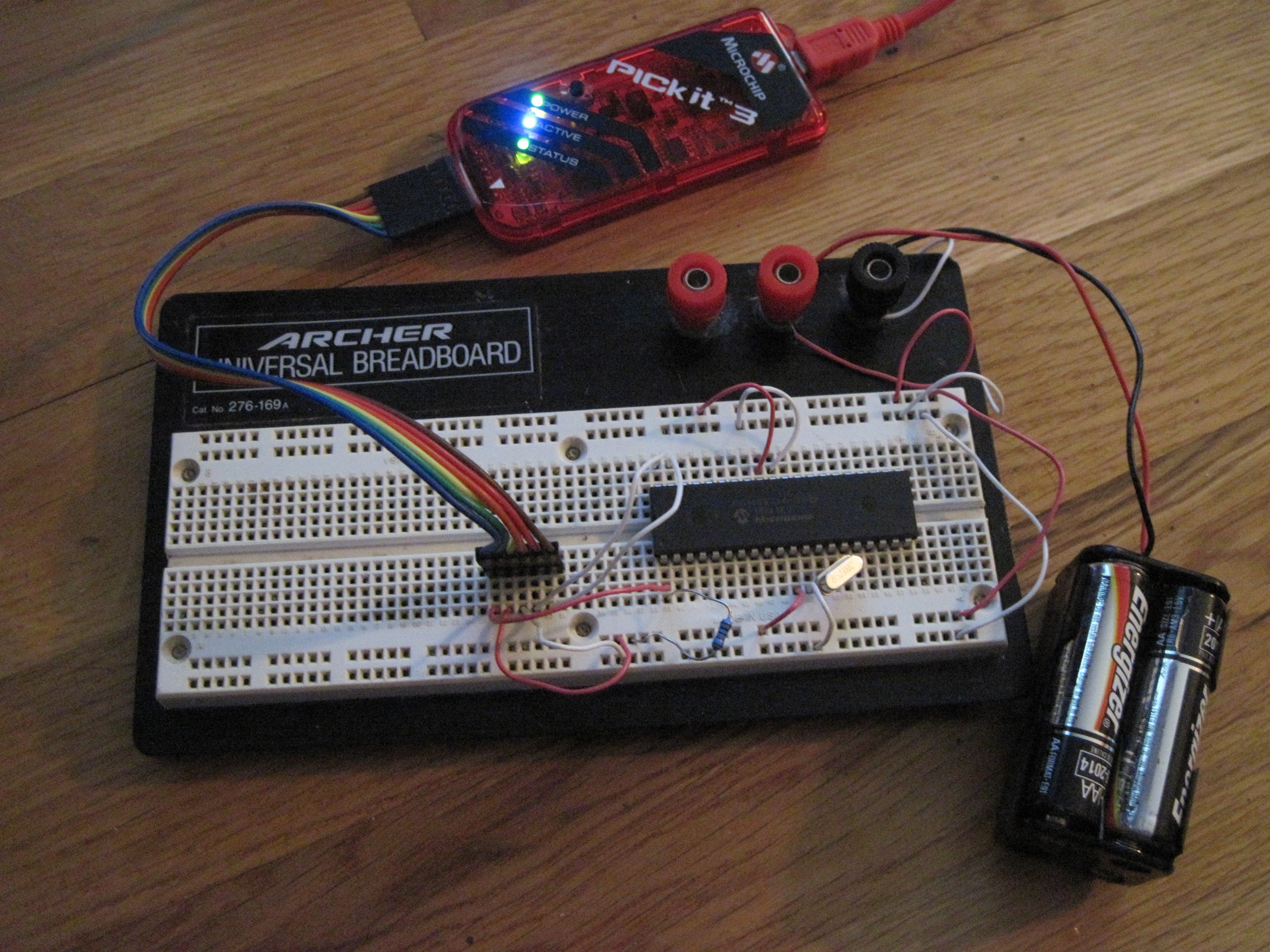
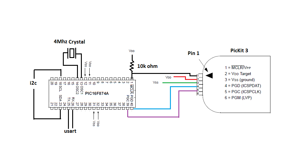
To allow other users to experiment with the Squid board, each PIC will have an in-circuit serial programming port. The sub routines to handle all the features like usart for the Bluetooth and serial interface, I2C to communicate between the 2 PICs and other peripherals, A to D converter will be provided as an include file. This will allow other makers to program the Squid to control whatever project the user wants to experiment with while easing the work load by already having callable sub routines to use the on board features.
The default configuration for the 16 H-bridges will be as individual drivers to control 16 individual small dc motors. A configuration option will be provided to allow two H-bridges to be “bonded” as a 4 channel driver to control either a 4 phase unipolar step motor or a 4 phase bipolar step motor. In case the 16 H-bridges is not enough, an I2C interface will allow the Squid to interface with other Squid boards or other peripheral devices.
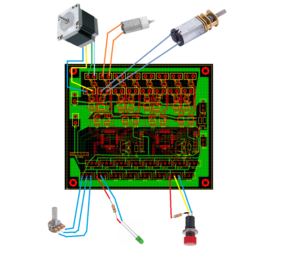
The image below shows typical connection. Configurable inputs--the LED shows a digital output, the potentiometer shows an analog to digital input and the switch shows a digital input. The configurable motor drivers show a connection for a step motor and connections for small DC motors. The idea is to make an easy to use robotics motor control board to Bluetooth to higher level controllers, such as a Raspberry Pi. There is also a serial port for controllers without a Bluetooth module, plus plenty of available onboard FLASH memory can be programmed for standalone operation to allow the Squid to control a robot without a higher level controller.
Agenda:
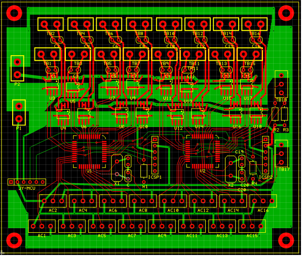
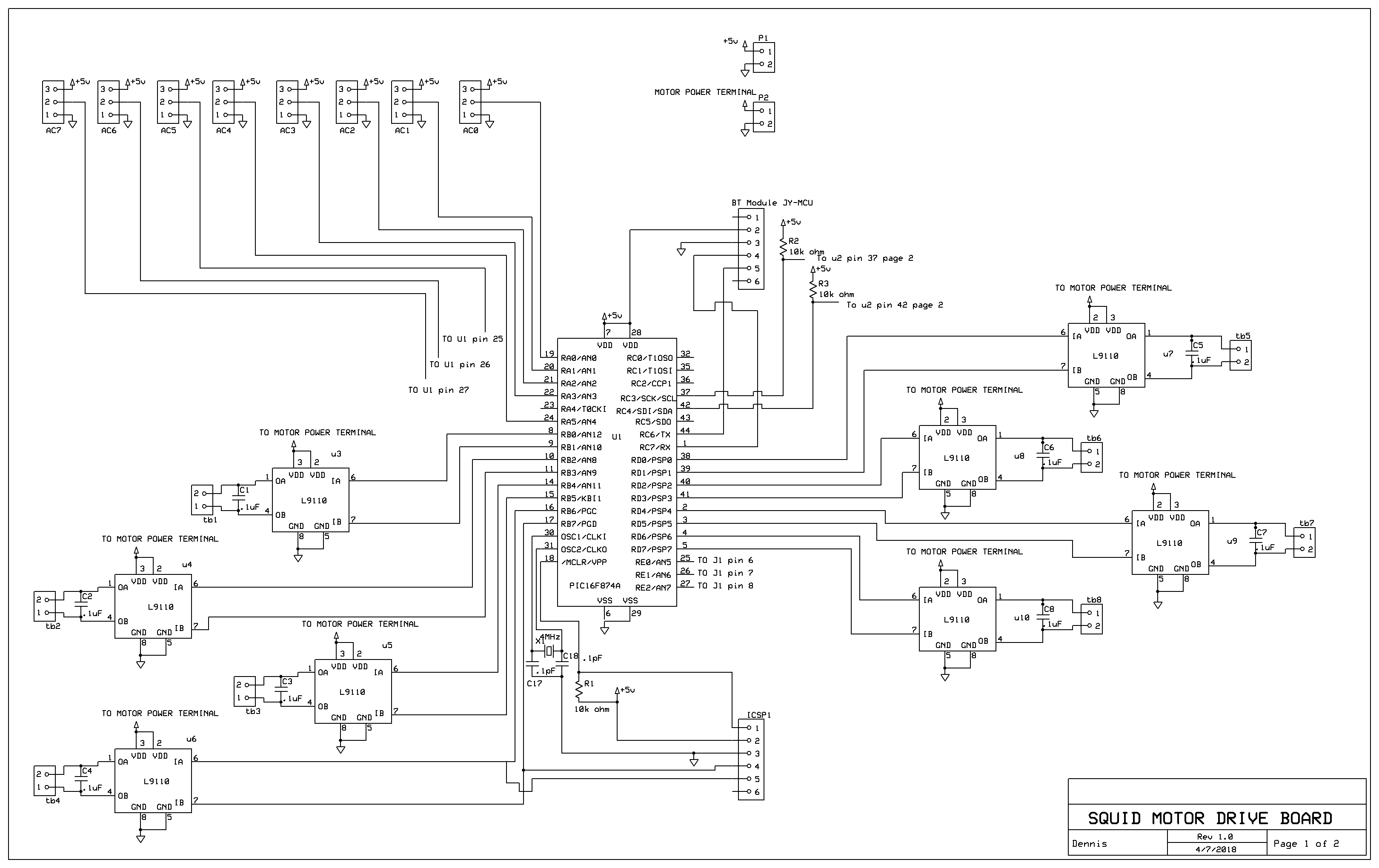
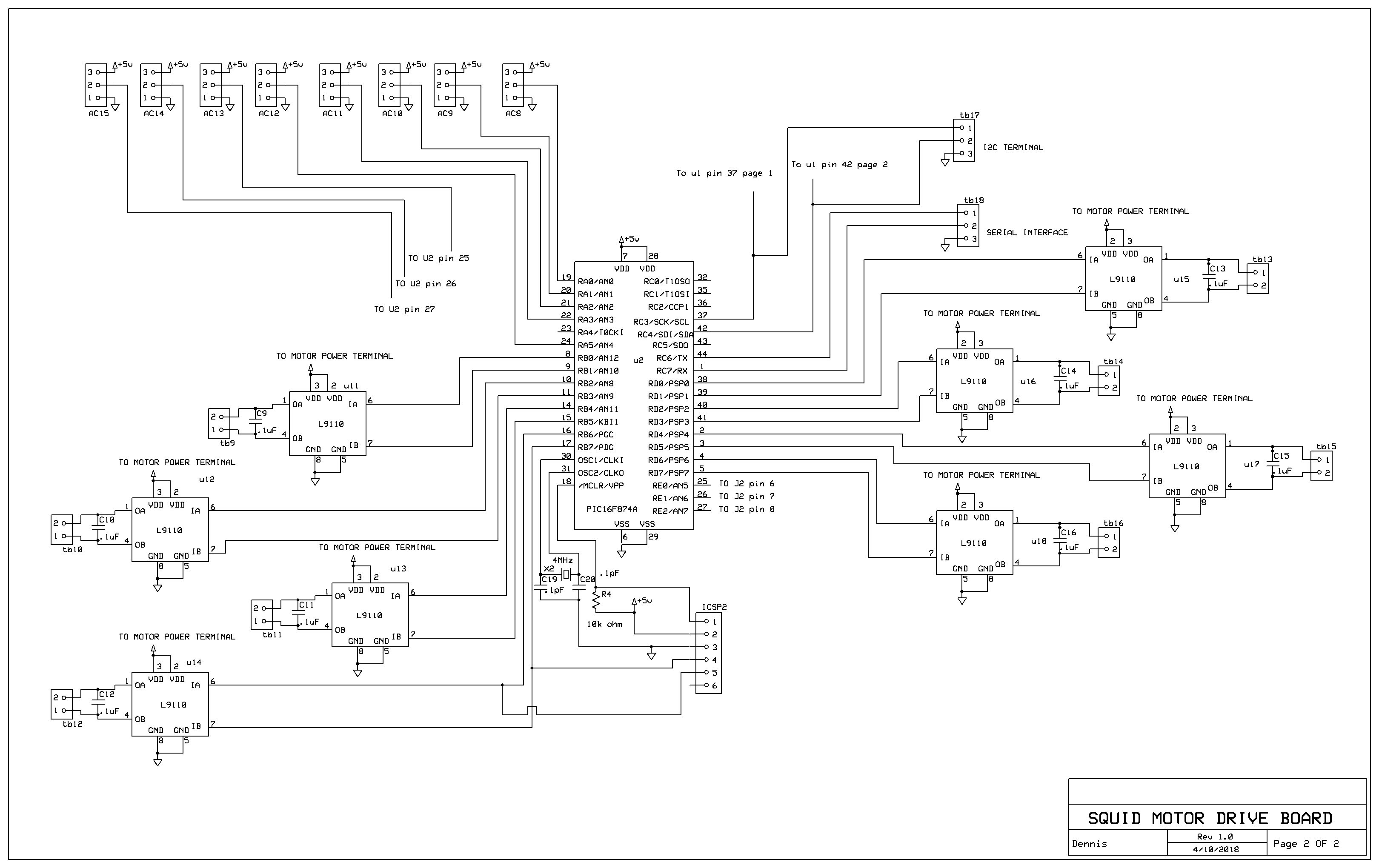
Schematics
Board layout
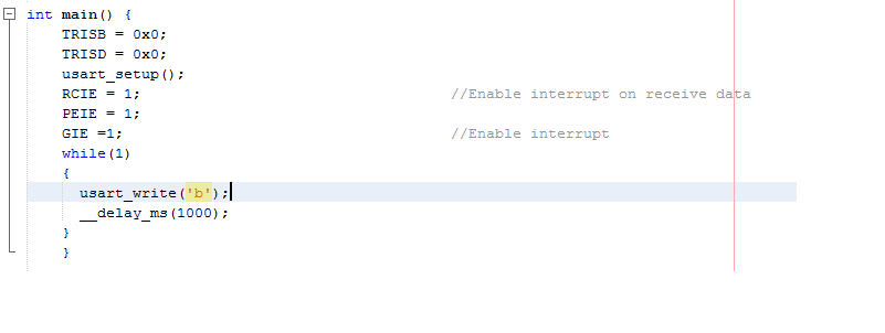
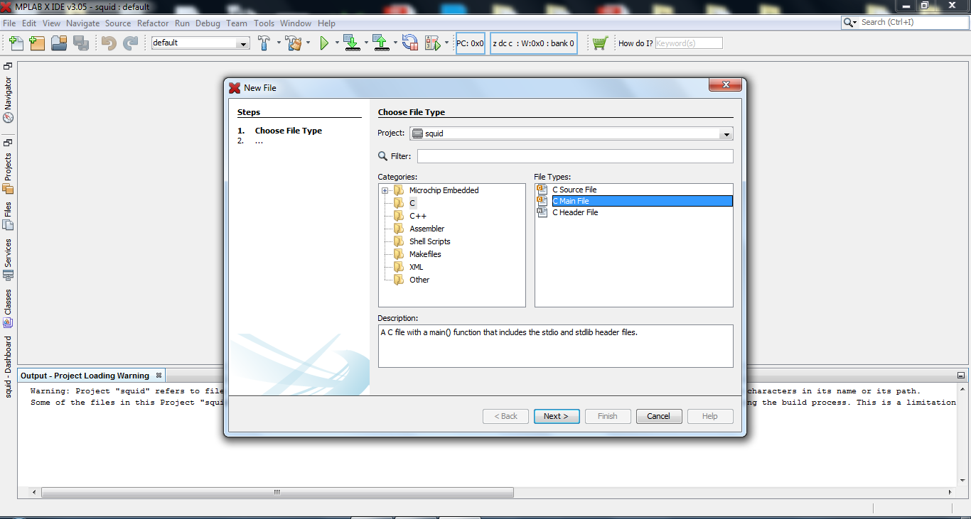
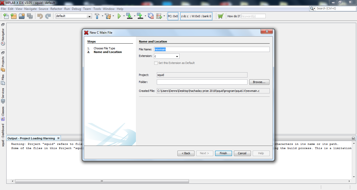
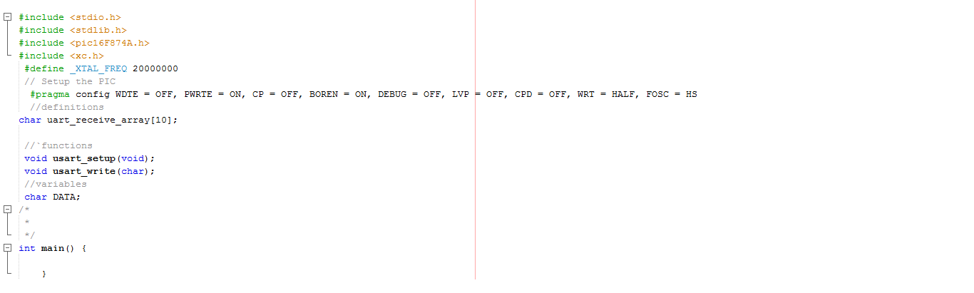
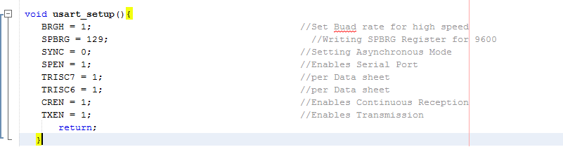
Software subroutines for MicroChip PIC onboard resources.
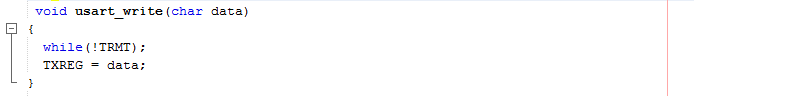
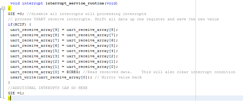
- USART interface for Bluetooth and direct connect serial interface.
- I2C interface to communicate between the PICs and other peripherals.
- Analog to digital converter.
- EEPROM routine to store to and read from PIC onboard EEPROM for configuration data.
Software routine to control small DC motors.
Software routine to control four phase unipolar step motors.
Software routine to control four phase bipolar step motors.
Software routine to organize I2C devices.
Software routine to receive and save configuration data.
Software routine to interpret commands from an external controller.
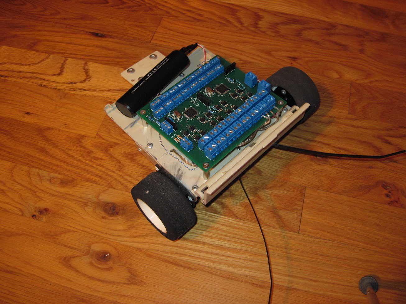
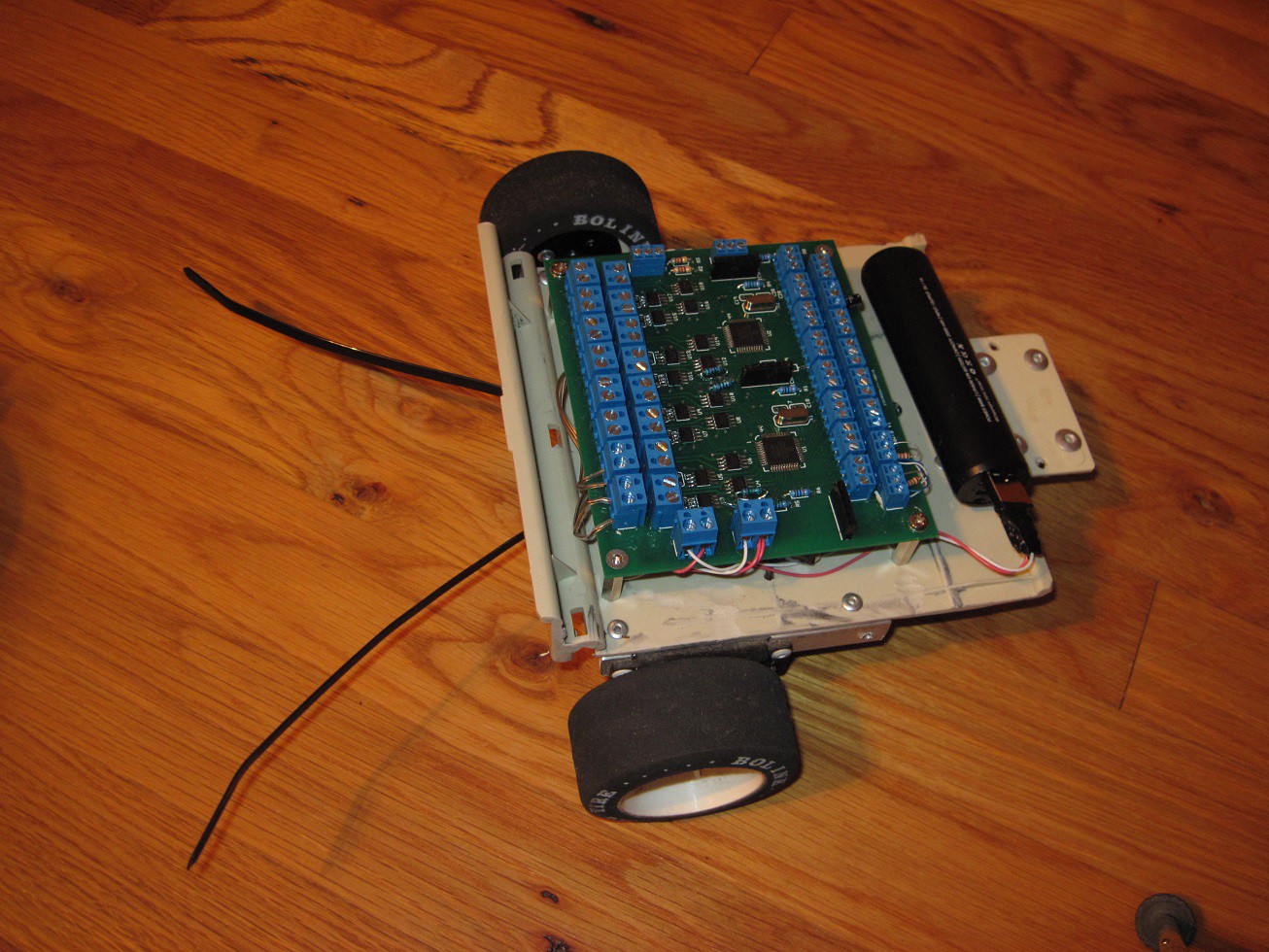
The videos below shows the Squid as a stand alone controller.

 Phil Malone
 Redtree Robotics
 Fangzheng Liu
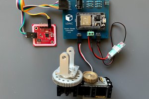
 Udi Cohen
hi
i didn't ask :
how many amps per phase it will support ?
thanks