Close
0%
0%

NekoCal - an E-Ink Calendar

A simple calendar made with e-ink display and stm32 microcontroller.

Similar projects worth following
A simple calendar made with e-ink display and stm32 microcontroller. Can display date&time and a background image. Images are stored in the SD card. The ultra-low power consumption and always on display make it perfect for basic information display purpose. Next step would be trying to use an ESP-32 to replace the STM32F4 make it possible to grab information from the internet.

Hardware specs:

Rev1:

Processor - STM32F407ZET6

Memory - 512K * 16bit SRAM

Rev1.1 (cost down):

Processor - STM32F407VGT6

Memory - All moved to internal SRAM

Screen - ED060SC4 800*600 EPD (working in 16-level greyscale mode)

Features:

Display the Date & Time of course.

Display BMP from SD card as a background.

Probably use it with Raspberry Pi?

Driving details:

Up to 16 shades of grey. Full refresh & partial refresh. Full 800*600 resolution

Fast response 1-bit mode available (Up to 10fps+, depending on the screen used)

See source code for detail. Software driven, no special controller used.

An write-up about the EPD driver program in the project log, check it out!

  • 1 × STM32F407VG Microprocessors, Microcontrollers, DSPs / ARM, RISC-Based Microcontrollers
  • 1 × DS3231 Clock and Timer ICs / Real-Time Clocks
  • 1 × LT1615 Power Management ICs / Switching Regulators and Controllers
  • 1 × ED060SC4 PVI 800*600 EINK Panel

  • Can you get 32 level grayscale out of an E-ink display?

    Wenting Zhang12/31/2017 at 01:54 1 comment

    A quick research shows that all current commercial E-ink devices have a maximum grayscale level of 16. Is it a hardware limitation? Or is it possible to get more grayscales just like people have done on CGA, Commodore 64, GameBoy Color and many other vintage hardware that have a color limitation?

    Well, the answer is yes. See my results :p

    Just as said on the screen, happy new year 2018! (The upper right is one in 4bpp mode for reference)

    Now, how it is done? Basically, to display an image on an Eink display, one need to apply multiple frames to the screen, and the result of superposition would be the image. In order to decide what to apply to display a specific color, a look-up table is used, and it is called “waveform table”. This is usually provided by the driver solution provider and I have no direct access to it as it is confidential. Now all commercial displays can only do 4bpp because there is simply no 5bpp LUT available.

    So if I can create one and it would be able to do 5bpp right? Yes, but only if I can. The waveform table is actually a 4 dimension LUT, the output depends on the previous grayscale, the target grayscale, the current frame number in a series of superposition, and temperature. Basically it’s just way too hard for me to create such a LUT. Maybe this is also the reason why there is no commerical 5bpp LUT available?

    So in order to archive that, I need to first “trim down” the LUT. 4D is way too much. Firstly, I decided to ignore the temperature. Then we can always start at white. Now it is already a 2D LUT. Then I decided to make the target grayscale equals to the frame number: I would use fixed 32 frame sequence for 5bpp mode and one frame correspond to one level grayscale. This requires a big change to the LUT: It is no longer looking up for the data to output since we have made it match, the output have to equal to the grayscale input. So instead it is looking up for the line time. By adjusting the line time we can fine control the grayscale. And here it is.

  • Bad Apple on an E-ink ?

    Wenting Zhang12/30/2017 at 01:04 1 comment

    Well, just for fun, here it is. The video has been sped up for sure. In reality, the E-ink screen refreshes at a frame rate of around 2.4fps, so a 10X speed up gives this nice and fun effect.

  • A comparison between ED060SC4 and ED060SC4 H2

    Wenting Zhang04/26/2017 at 03:42 2 comments

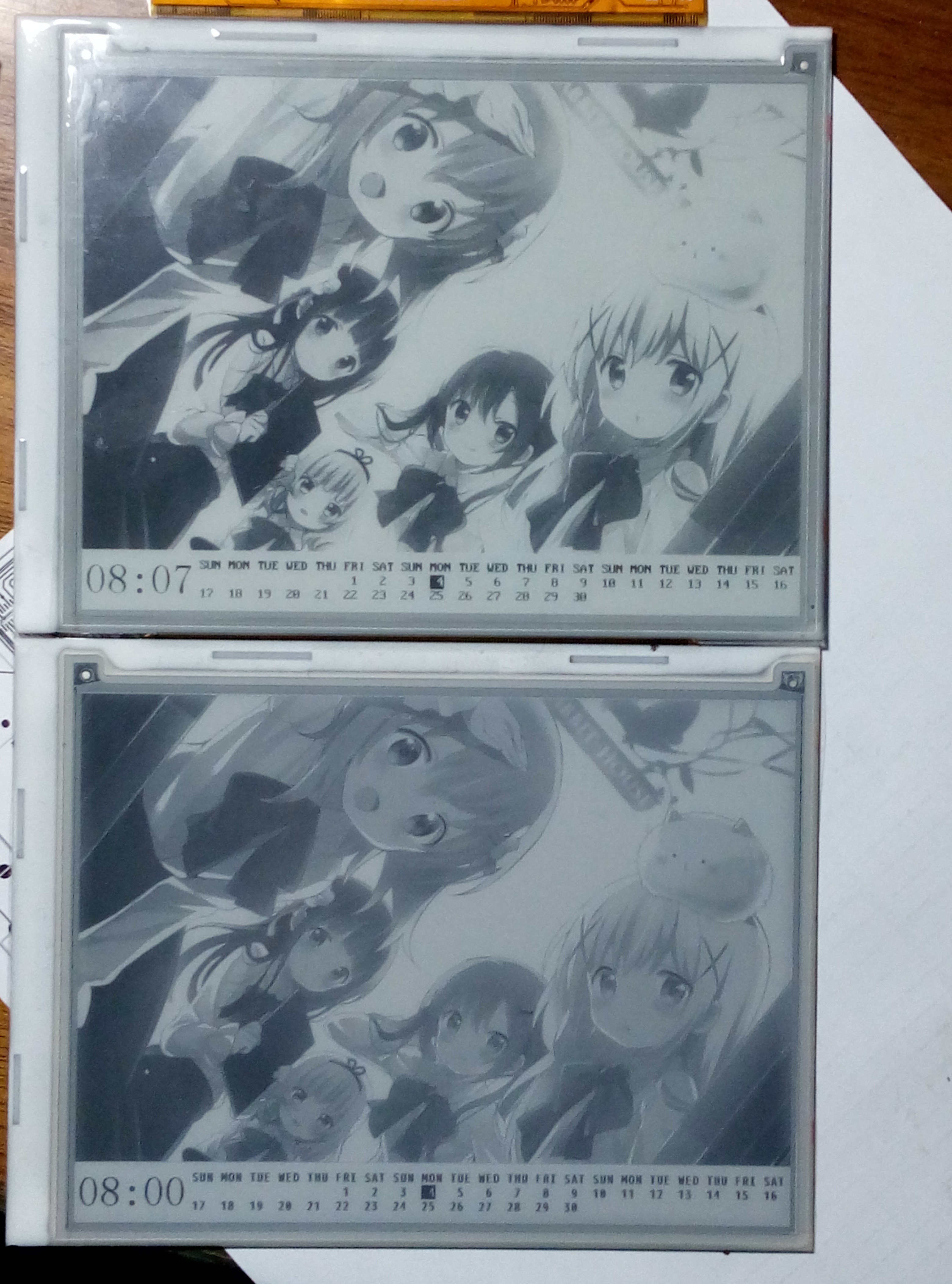
    The upper one is ED060SC4 H2 and the lower one is ED060SC4. See that difference. H2 screens have higher contrast ratio and faster response. But I would need to adjust the Gamma LUT for the new screen.

  • A description about the EPD driving method used in this project

    Wenting Zhang12/13/2016 at 03:13 1 comment

    The EPD screen is called E-paper because once it is finished "printing", it will retain the content even if the power is disconnected. So as you can imagine, when we actually driving the EPD screens, we have three different operations: write (encoded 0b01), wipe (encoded 0b10), leave it as is (encoded 0b00). The first operation will turn a white pixel into black, the second will turn a black pixel into white and the third will do nothing. More about these operations later. But there is a big drawback of EPD displays, that is the EPD pixel need some time to turn itself from black to white or from white to black. And that time is usually more than 300ms so we say EPD have a long response time.

    However, the EPD is usually refreshed at a higher frame rate, like 60Hz. So you can see under 60Hz setting, the pixel won't be able to fully turn around in one frame. So there are two ways, one if lower down the refresh rate, aka keeping one frame longer, another is adding more frames. For an example, if your screen have a response time of 1/3s(333ms), you can either lower the frame rate to 3Hz or send 20 same frames under 60Hz. My driver used the later method. The reason is that when using the first method, you can actually see the screen refreshed up to down since the data is being sent in that speed. The second method (more frames) would not have this effect. You see the whole screen get refreshed together. (though actually still up to down but you can't see) So here it the full idea: assume we start from a white screen which have a resolution of 2px * 1px, and we want it to display something like, one light pixel followed by a dark one: [ *]. So for the first pixel, it's already white (we start from white), so send the third operation (leave it as is) to the screen. For the second pixel, it need to be black, so we send the first operation (write) to the screen. And that’s one frame, we are running under 60Hz, so send 20 times. And we should get would we hoped.

    But what if you stop driving a pixel before it totally turned around? Like, we send only 10 frames in the last example. The answer is that it would stay gray. And that's the fundamental of grayscale display on EPD panels. By controlling the driving time, we can create 4 shades or even 16 shades of gray. My driver used 4bpp(16shades) mode for better image quality, but if you can understand the principle, you can easily modify it to 4 shades or maybe 32 shades. Okay here is the thing. In 4bpp mode, there are 16 shades of gray. Let's continue with the assumption we made about the response time, 1/3s and begin with a white screen. If we evenly divide 1/3s into 15 slices, which is 1/45s each. So then we turn the frame rate to 45Hz, so one frame is 1/45s. For the pixel that's black, it’s obvious we want to send “write” command to the screen for 15frames, and it would turn black. For the pixel that’s white, just send “leave as is” in all 16 frames, it would leave white. That’s essentially the same as before. But if we want it to be the first shade of gray (which is, 1/15 of the brightness, note that 15/15 is black and 0/15 is white), simply send “write” in the first frame and “leave as is” in all other frames. So, the fourth shade of gray would be 4 frames of “write” plus 11 frames of “leave as is”. So what if we want 32 shades of gray? Adjust the frame rate to 93Hz and we are almost ready to go.

    Unfortunately, things are not that easy. First of all, our STM32 software driving method is unable to achieve a refresh rate of 60Hz. Actually it can do only about 12Hz. So 4 frames is enough to drive the pixel from black to white or from white to black. It would be fine if I stick with monochrome mode or 2bpp (4-level) grayscale mode. But what if I want to do 4bpp mode, I have to use some tricks. Normally, the MCU send the data to source driver of the screen, when finished sending, it let the source driver latch the...

    Read more »

View all 4 project logs

Enjoy this project?

Share

Discussions

oleedee wrote 09/20/2017 at 11:31 point

This looks great!
Can anyone recomend a good source of info for getting started programming on e-ink? I have writen successfully for OLED before so I think it may be similar. I cannot wait to get tinkering with a screen like the one you are using.

Thanks,

  Are you sure? yes | no

PaulWoooong wrote 09/14/2017 at 10:03 point

可否做一个 Kindle DXG 9.7inch  usb 外部屏幕?  用 arduino 做无线usb接口。

  Are you sure? yes | no

PaulWoooong wrote 09/14/2017 at 07:00 point

As a calendar, it's a waste of use of the ink screen. I do suggest upgrade it to a wireless external usb monitor, and using the Kindle DXG 9.7 inch screen instead. 

  Are you sure? yes | no

Devin E. wrote 09/02/2017 at 08:39 point

I actually have a Nook (that just so happens to have an ED060SC4 H2) that I bought a while ago for dirt cheap with the original purpose of restoring the Nook (bottom lcd is bad)...but this is so much cooler! I hope that this project turns out well for you guys!

  Are you sure? yes | no

Starhawk wrote 04/26/2017 at 20:21 point

Aaaaaaaaah I want one!

  Are you sure? yes | no

Yvan256 wrote 12/13/2016 at 04:14 point

An e-paper project AND anime pictures! Great! ^_^

  Are you sure? yes | no

Lars R. wrote 08/30/2016 at 06:03 point

Any updates, new photos of REV2?

Could it have UART for graphics input?

Could you sell the board (ebay, aliexpress,...)?

  Are you sure? yes | no

borazslo wrote 09/07/2016 at 06:39 point

+1

  Are you sure? yes | no

Will Whang wrote 05/02/2016 at 12:49 point

Oh my god,這太猛了

  Are you sure? yes | no

Similar Projects

Does this project spark your interest?

Become a member to follow this project and never miss any updates