Wenting Zhang
-
Basics of driving E-paper displays
03/30/2021 at 01:59 • 2 commentsIntroduction
Hi, how's going? I haven't written anything about this project for a long while. I was thinking about making a better version of this, that could support more displays, has an open API, support wireless communication like WiFi, LoRaWAN, etc. But I didn't have the time to pull that off. Instead, I made my code open and wrote a log to describe how to get greyscale when driving these screens directly with an MCU such as STM32 or ESP32 (which no one explored before). I am glad to see the communities were able to take what I have done and built the thing that I wanted to build: the EPDiy project. And there are emerging projects like ei2030's E-ink laptop that are aiming to take the E-ink DIY idea further.
However, people who are new to the whole E-ink DIY thing might be confused: there are so many screen choices. Some require quite sophisticated driving boards, others don't. There are boards that could be connected to an Arduino, and there are also boards that would simply accept standard HDMI inputs. Are they compatible? What are the advantages and disadvantages of different driving schemes?
I am writing this log, to describe some of the basics of driving E-ink/E-paper displays. Hopefully, this could be helpful.
Components
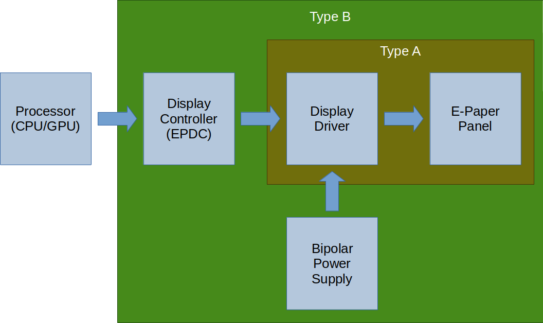
For any E-paper display devices, it needs the following components:
![]()
Every system needs these components. However, they could be integrated, so one may not be aware of these. One common technology used in screens nowadays is called "Chip On Glass", or COG for short. It allows integration chips on the glass panel. Virtually all E-paper displays use this technology to integrate some parts of the system onto the glass. (If EPDs were commercialized 10 years earlier, you would see other technologies being used in place of COG, such as TAB, or COB, etc.)
Most of the screens available today can be divided into two categories based on what is integrated into the glass panel, as shown in the diagram as Type A and Type B.
Note: The type A/B name is made up by myself, there is no standard way of calling them AFAIK.
The type A screen integrates only the display driver chips, however, the type B screens integrates almost every chip you need to use the screen.
Here is a non-exhaustive list of the type based on their size: (the size or resolution is not related to or limited by the type, it is just for a certain size, the vendors tend to make them the same type.)
Type A (driver-only)
- 4.3" panels (both 800x480 and 800x600)
- 6.0" panels (both monochrome and ACeP)
- 7.8" panels (both monochrome and ACeP)
- 9.7" panels
- 10.3" panels
- 13.3" panels
Type B (fully integrated)
- 1.02" panels
- 1.54" panels
- 2.13" panel
- 2.6" panels
- 2.9" panels
- 3.71" panels
- 4.2" panels
- 5.83" panels
- 7.5" panels
- 12.48" panels
One may notice that almost all e-readers/ e-ink cellphones use Type-A screens, while almost all e-ink electronic shelf labels (ESL) uses Type-B screens. This gives some hints about the advantages and disadvantages of two types:
Type A (driver only) Type B (fully integrated) System Cost High. A dedicated controller usually needed. Needs a dedicated power supply. Low. Virtually any MCUs could drive the screen directly Greyscale Levels Generally 16 (4bpp), up to 32 (5bpp) Generally 2 (BW only) or 4 (2bpp), with some hack, up to 16 (4bpp) Refresh Speed Generally fast (100ms~600ms), depending on the screen used and the system architecture Generally fast (100ms~300ms) for BW if the partial refresh is enabled. Greyscales much slower, BWR or BWY screens would be even slower. Total Update Latency Generally the same as refresh time. Depends on the system architecture Slow. Ranging from 100ms to 10s based on the resolution. Note that I mentioned the refresh speed and total update latency. How they are different?
The refresh speed refers to the time it takes to start refreshing the screen: from starting seeing screen changing, to the screen finish showing the new content.
The total update latency refers to the latency when the processor needs to update the screen, to the screen finish showing the new content. As you could see, this is the biggest issue for Type B displays. This is the main reason why they are almost never used on e-readers or cellphones or PC monitors.
Driving type-B / fully integrated screens
This is fairly simple. Type-B screens have almost everything already integrated. Common type-B displays only need few external capacitors, inductors, and MOSFETs to support the integrated bipolar power supply circuit, then it could be hooked up to MCUs or MPUs using common interfaces like SPI or I2C. There are a lot of driving boards and examples of these screens available online. As they are basically the same, I will not go into details about them.
Driving type-A / driver-only screens
This could get complicated. Note I used a lot of "generally" in the comparison chart because there are many things you could do to drive them. Some of them would certainly impact the performance. The main issue here the controller chip. There are two types of commercial solutions to drive these screen:
- Using a dedicated controller chip to drive the screen
- Using an SoC that has an integrated controller
And then... there is a third way, a low-cost and more accessible way of driving these screens:
- Using a fast MCU/SoC to emulate the controller with GPIO (software timing controller)
Then, again here is a comparison between them:
Specialized controller chip SoC with integrated controller MCU + Software TCON Resolution UXGA+ UXGA+ Limited by MCU RAM. Up to XGA with SRAM, UXGA with PSRAM, UXGA+ with DDR Greyscale 16 16 Up to 32 Partial Update Yes (monochrome and greyscale) Yes (monochrome and greyscale) Yes with vendor waveform (monochrome and greyscale) and open-source waveform (currently monochrome only) Waveform support Vendor waveform or open-source waveform if open-source controller chip is used Vendor waveform only. Might could work with open source waveform as well with some hack Vendor waveform and open-source waveform Total Update Latency Depends. Could be very close as refresh speed, could be slow like Type-B screens Same as refresh speed. Same as refresh speed if data is internally generated. (not streaming from an external device such as a PC) Suitable Applications IoT devices,
E-readers, cellphones,
E-ink monitors.
possibly E-ink laptopsAdvanced IoT devices, E-readers, cellphones,
E-ink typewriters,
possibly low-performance E-ink laptopsWhen using MCU: IoT devices, large ESLs, simple DIY E-readers
When using MPU: Same as SoC with integrated controllerSome additional notes about some of the items in the table:
About waveform...
The waveform is a look-up table that the controller uses to determine how to drive the screen. Features like greyscale display and partial updates are enabled by sophisticated waveforms. This is an essential part of any e-ink controller. There are two different types of waveforms: vendor waveform and open-source waveform.
Vendor waveforms are copyrighted material. Think them of like the BIOS or ROM of the game consoles. Issues with console emulators apply here: one cannot distribute them legally. Currently, they are protected by NDAs, so not easily obtainable from the vendor. Dumping the waveform would require buying a commercial device and extract by the end-user.
Open-source waveforms are created by the community as a replacement to be used in open-source projects. They are created with cleanroom technology (at least the ones used in my project are entirely crafted by hand by myself. I have never reverse engineered any vendor waveforms.) so they are not copyrighted by vendors. However, they are limited in performance, missing critical features, and might not compatible with vendor waveforms (thus not compatible with controllers designed to work with vendor waveforms).
Waveforms are interchangeable between different screens to some extent. The screen would work with a non-optimal waveform, but the image may not show the correct color (gamma, brightness, etc), the ghosting could be more noticeable.
About update latency again...
The latency, is composed of 2 parts: the time it takes for the processor to transfer the image to the controller, and the time it takes for the controller to drive the driver to display the content on to the screen.
The reason Type B screens are slow is that, they tend to use slow protocols to talk to the processor. For example, the most common one is the SPI, could only transmit up to ~20Mbps. For a 1024x758 panel at 4bpp, it takes 1024 * 758 * 4 / 20000000 = 150ms to transmit the image, would be worse if SPI is running at slower speed or . This adds 150ms to any frame to be displayed.
For Type A screens, it really depends on the controller used.
If using SoC with integrated controller, or MCU direct drive scheme, the image is always already in the RAM local to the controller. The latency is just the latency to access the RAM, which is usually less than 200ns and can be ignored.
If using a dedicated controller, it depends on how the controller is connected to the processor just like Type B screens, but you have more choices.
For example, controllers like IT8951 or S1D13xxx supports i80/68K parallel interface, which brings down the latency to like 20ms. Controller that supports DPI/ DSI/ HDMI interface, depends on the implementation, the latency could be 1 frame (16.7ms) or just 1 line (~20us).
About the suitable application...
When using a dedicated controller, it could accept data from external devices. This allows it to be used in various different types of applications. Ranging from IoT devices, ESLs just like when using Type B displays, to PC monitors with relatively fast refresh rate and low latency.
When using SoC or MCU, the display content is generated by the SoC or MCU itself, which ultimately is limited by the capability of the SoC or MCU. Given the current SoCs with E-ink display controllers are quite limited in performance, the application is limited. The same goes for MCU, it does what an MCU could do. You could find ways to stream video data into SoC or MCUs by using USB, camera interface, WiFi, etc., but this might not be optimal.
List of the available solutions by driving scheme:
- Specialized controller chip
- Closed-source / Commercial
- EPSON S1D13xxx: Widely used EPD controller in early E-readers. Proprietary, no documents available. Probably EOL.
- IT8951: Used on waveshare EPD Hat. Documents available, work with large EPDs. The drawback is the speed. Using IT8951 with a large Type-A EPD effectively turns it in to a Type-B like screen, with high update latency (interface between processor and IT8951 could be slow)
- Waveshare HDMI driver board: FPGA-based controller. Closed source but easily purchasable, could be integrated into larger projects as a module.
- Dasung E-ink monitors: Not sure. FPGA + some proprietary controller.
- Open-source
- https://hackaday.io/project/21607-paperback-a-desktop-epaper-monitor: FPGA-based controller. However, doesn't support partial update mode.
- https://hackaday.io/project/21168-fpga-eink-controller: Seems to be working. Not sure about the state.
- Closed-source / Commercial
- SoC with integrated controller
- RK29xx: Fairly old, Cortex-A8 based (RPi 1 level performance), 55nm, EOL
- RK3026/RK3028: Fairly old, Cortex-A9 based (RPi 2 level performance), 40nm, EOL
- i.MX 50: Fairly old, Cortex-A8 based (RPi 1 level performance), 65nm, in production
- i.MX 6S/D: Fairly old, Cortex-A9 based (RPi 2-3 level performance), 40nm, in production
- i.MX 7S/D: Cortex-A7 based (RPi 2 level performance), 28nm, in production
- i.MX 8ULP: Cortex-A35 based (RPi 2 level performance), 28nm FD-SOI, sampling
- RK3566/RK3568: Cortex-A55 based (RPi 3 level performance), 22nm, in production Note none of them are confirmed to work with open-source waveform. I am not aware of any open-source hardware (as defined by OSHWA) projects built with these processors utilizing an e-ink screen.
- MCU/SoC + Software TCON
- http://essentialscrap.com/eink/waveforms.html: One of the earliest e-ink hack. Limited in performance but still could be used as a reference
- This project (NekoCal): One of the earliest e-ink software TCON with greyscale support. Used to be available as a DIY kit. No longer updated, still could be used as a reference
- InkPlate 6/10: Commercially available. Based on ESP32.
- EPDiy: Based on ESP32, supports a lot of different screens, recommended if want to build some device with ESP32+Eink or embedding it into a larger project.
- Many new BOOX ereaders, using software driver + parallel LCDIF to drive the screen
Conclusion
Hopefully this log clarifies some of the confusions or answers some of the questions. There are different types of displays and different ways to drive the screen. They come with their advantages and disadvantages. There is no single best way of doing things, it all depends on the requirement of the target application.
-
Can you get 32 level grayscale out of an E-ink display?
12/31/2017 at 01:54 • 1 commentA quick research shows that all current commercial E-ink devices have a maximum grayscale level of 16. Is it a hardware limitation? Or is it possible to get more grayscales just like people have done on CGA, Commodore 64, GameBoy Color and many other vintage hardware that have a color limitation?
Well, the answer is yes. See my results :p
![]()
Just as said on the screen, happy new year 2018! (The upper right is one in 4bpp mode for reference)
Now, how it is done? Basically, to display an image on an Eink display, one need to apply multiple frames to the screen, and the result of superposition would be the image. In order to decide what to apply to display a specific color, a look-up table is used, and it is called “waveform table”. This is usually provided by the driver solution provider and I have no direct access to it as it is confidential. Now all commercial displays can only do 4bpp because there is simply no 5bpp LUT available.
So if I can create one and it would be able to do 5bpp right? Yes, but only if I can. The waveform table is actually a 4 dimension LUT, the output depends on the previous grayscale, the target grayscale, the current frame number in a series of superposition, and temperature. Basically it’s just way too hard for me to create such a LUT. Maybe this is also the reason why there is no commerical 5bpp LUT available?
So in order to archive that, I need to first “trim down” the LUT. 4D is way too much. Firstly, I decided to ignore the temperature. Then we can always start at white. Now it is already a 2D LUT. Then I decided to make the target grayscale equals to the frame number: I would use fixed 32 frame sequence for 5bpp mode and one frame correspond to one level grayscale. This requires a big change to the LUT: It is no longer looking up for the data to output since we have made it match, the output have to equal to the grayscale input. So instead it is looking up for the line time. By adjusting the line time we can fine control the grayscale. And here it is.
-
Bad Apple on an E-ink ?
12/30/2017 at 01:04 • 1 commentWell, just for fun, here it is. The video has been sped up for sure. In reality, the E-ink screen refreshes at a frame rate of around 2.4fps, so a 10X speed up gives this nice and fun effect.
-
A comparison between ED060SC4 and ED060SC4 H2
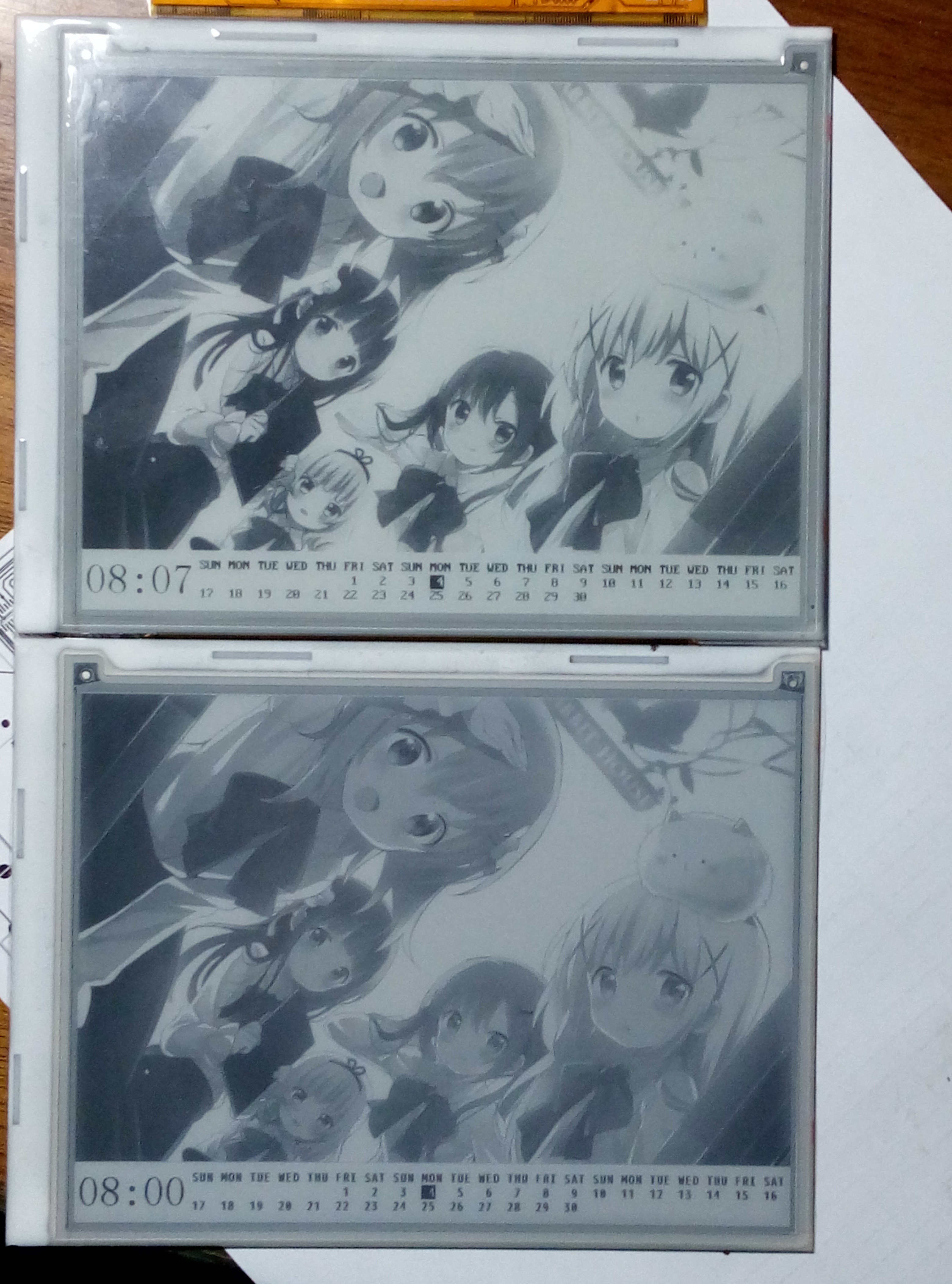
04/26/2017 at 03:42 • 2 comments![]()
The upper one is ED060SC4 H2 and the lower one is ED060SC4. See that difference. H2 screens have higher contrast ratio and faster response. But I would need to adjust the Gamma LUT for the new screen.
-
A description about the EPD driving method used in this project
12/13/2016 at 03:13 • 1 commentThe EPD screen is called E-paper because once it is finished "printing", it will retain the content even if the power is disconnected. So as you can imagine, when we actually driving the EPD screens, we have three different operations: write (encoded 0b01), wipe (encoded 0b10), leave it as is (encoded 0b00). The first operation will turn a white pixel into black, the second will turn a black pixel into white and the third will do nothing. More about these operations later. But there is a big drawback of EPD displays, that is the EPD pixel need some time to turn itself from black to white or from white to black. And that time is usually more than 300ms so we say EPD have a long response time.
However, the EPD is usually refreshed at a higher frame rate, like 60Hz. So you can see under 60Hz setting, the pixel won't be able to fully turn around in one frame. So there are two ways, one if lower down the refresh rate, aka keeping one frame longer, another is adding more frames. For an example, if your screen have a response time of 1/3s(333ms), you can either lower the frame rate to 3Hz or send 20 same frames under 60Hz. My driver used the later method. The reason is that when using the first method, you can actually see the screen refreshed up to down since the data is being sent in that speed. The second method (more frames) would not have this effect. You see the whole screen get refreshed together. (though actually still up to down but you can't see) So here it the full idea: assume we start from a white screen which have a resolution of 2px * 1px, and we want it to display something like, one light pixel followed by a dark one: [ *]. So for the first pixel, it's already white (we start from white), so send the third operation (leave it as is) to the screen. For the second pixel, it need to be black, so we send the first operation (write) to the screen. And that’s one frame, we are running under 60Hz, so send 20 times. And we should get would we hoped.
But what if you stop driving a pixel before it totally turned around? Like, we send only 10 frames in the last example. The answer is that it would stay gray. And that's the fundamental of grayscale display on EPD panels. By controlling the driving time, we can create 4 shades or even 16 shades of gray. My driver used 4bpp(16shades) mode for better image quality, but if you can understand the principle, you can easily modify it to 4 shades or maybe 32 shades. Okay here is the thing. In 4bpp mode, there are 16 shades of gray. Let's continue with the assumption we made about the response time, 1/3s and begin with a white screen. If we evenly divide 1/3s into 15 slices, which is 1/45s each. So then we turn the frame rate to 45Hz, so one frame is 1/45s. For the pixel that's black, it’s obvious we want to send “write” command to the screen for 15frames, and it would turn black. For the pixel that’s white, just send “leave as is” in all 16 frames, it would leave white. That’s essentially the same as before. But if we want it to be the first shade of gray (which is, 1/15 of the brightness, note that 15/15 is black and 0/15 is white), simply send “write” in the first frame and “leave as is” in all other frames. So, the fourth shade of gray would be 4 frames of “write” plus 11 frames of “leave as is”. So what if we want 32 shades of gray? Adjust the frame rate to 93Hz and we are almost ready to go.
Unfortunately, things are not that easy. First of all, our STM32 software driving method is unable to achieve a refresh rate of 60Hz. Actually it can do only about 12Hz. So 4 frames is enough to drive the pixel from black to white or from white to black. It would be fine if I stick with monochrome mode or 2bpp (4-level) grayscale mode. But what if I want to do 4bpp mode, I have to use some tricks. Normally, the MCU send the data to source driver of the screen, when finished sending, it let the source driver latch the data and actually drive the pixels. In the meanwhile, the MCU started sending the data of next line. When finished, the MCU latch the data and tell the gate driver to switch to the next line. So the line driving time is roughly the time of the process of data sending. Now the data sends too slow due to the slow CPU/GPIO, so it set a lower limit of driving time for me. But as I have said before, more grayscales need higher frame rate, which actually means lower driving time per frame. In the normal way, the driving time is roughly the reciprocal of frame rate. But by using a trick, we can break this relationship, make driving time much lower than the reciprocal of frame rate. It’s actually easy. When MCU finished send one line, it would latch the data, and wait for a short period t1 of time, then turn off the source driver. So when actually sending the data, the source driver is off, the actual driving time is that t1. This method would make the frame rate even lower and make it slower to display a image since the time when MCU is sending the data is “wasted”. But it turned out to be a great workaround for me since I don’t often refresh the screen.
The second problem is that the brightness vs time is not linear. For example, 7/45s of driving time is supposed to give us a brightness of 7/15, but actually maybe 1/2, there is a little offset. Well, offset is generally okay but the real problem is that some times some shades get too close to distinguish. Thus, many details are lost. Believe or not, it’s even easier to resolve this using the workaround I mentioned before than using the normal way. I simply added a look up table of t1, so different frames can even have different driving times! The result turns out to be great.
Last I want to just briefly mention the actual data sent to EPD. The EPD use 2bpp format. Note that 2bpp does not mean 2bpp grayscale. It only means that in transmission, 1 pixel use 2 bits. Remember the three operations I said in the beginning? I said encoded 0bxx, that’s the thing that is actually send to the EPD. For example if I send 0b01001000 (0x48) to the screen, it would “write” the first pixel, “wipe” the third pixel, and do nothing to the second and fourth pixel.
That’s all. I’m not a native speaker, if you had any trouble reading this, please contact me, thanks.
NekoCal - an E-Ink Calendar
A simple calendar made with e-ink display and stm32 microcontroller.