 Michael Wessel
For some more details, please visit the GitHub page of this project.
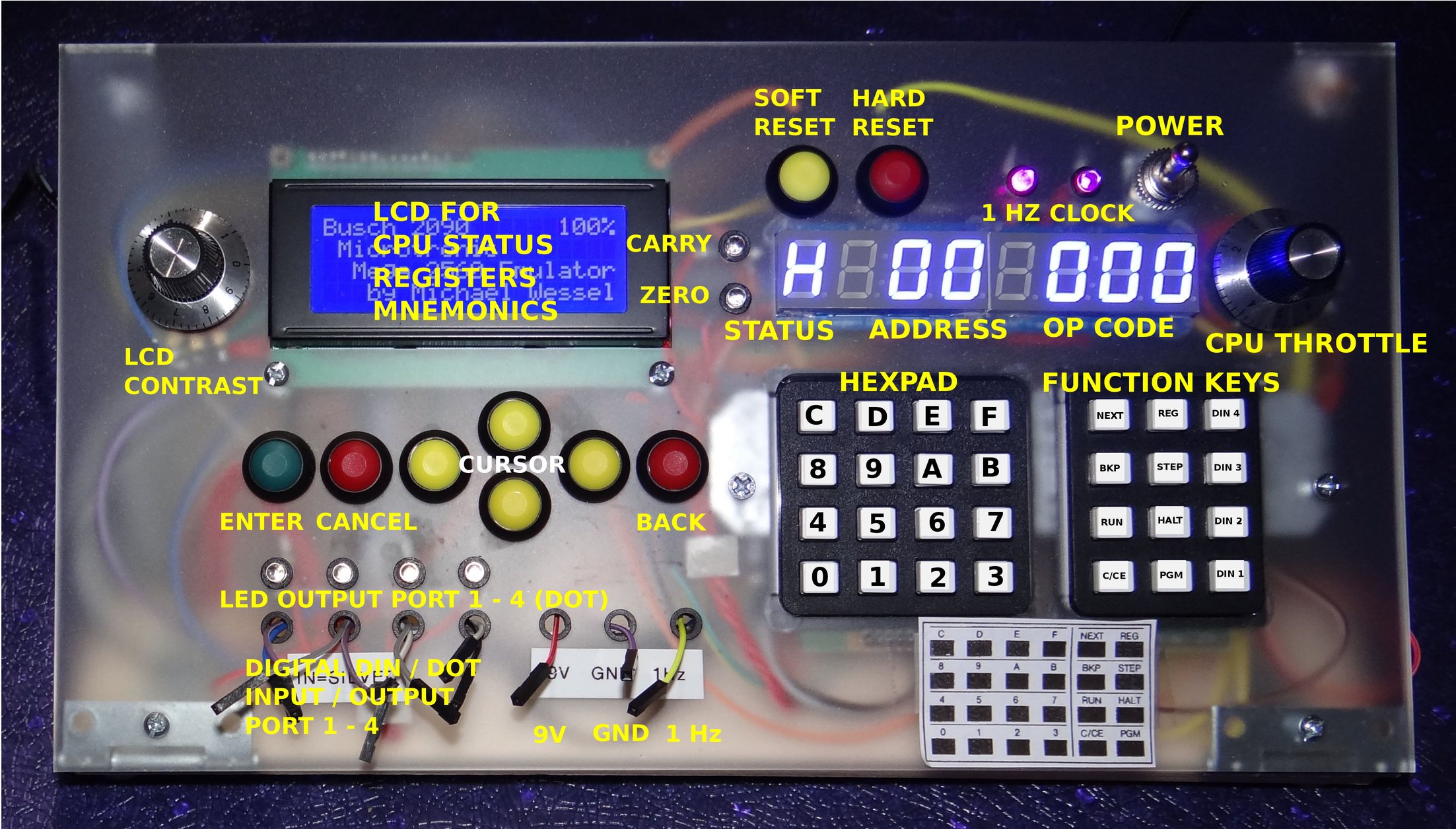
Explanation of Front Panel
Some YouTube Videos
Description of the Microtronic, its CPU and Machine Language
I was asked to provide some more details about the Microtronic and its machine language. Here we go:
The Microtronic is a very simple computer. It is programmed in a custom machine language, called 2090 ML in the following. 2090 ML is a virtual machine language, interpreted by the monitor program / operating system of the Microtronic. The original Microtronic uses a TI TMS 1600 Microcontroller, clocked at 500 kHz, and executes 2090 ML at a speed of a couple of 2090 ML instructions per second. This Microtronic Emulator runs on an Arduino Mega 2560, and the interpreter and operating system / monitor program was "reengineered" in C (I don't have the original TMS 1600 machine code of the operating system / monitor program). The emulator achieves a higher speed than the original Microtronic, but it can be throttled down with a pot.
The Microtronic program memory has 256 words of 12 bits. It has two sets of 16 universal 4 bit wide registers, 0 - F. There are instructions to swap / exchange the work and aux register sets. The CPU has Carry and Zero flags, and offers conditional and unconditional branching, as well as subroutines. The original Microtronic disallowed subroutine calls from subroutines due to the lack of a stack for storing the program counter, but my emulator allows nested subroutine calls (and the stack size is adjustable).
The 2090 ML was designed under didactic and pedagogic considerations, offering high-level instructions for otherwise tedious (or impossible) to implement operations, e.g., decimal multiplication and division, hexadecimal to decimal conversion (and vice versa), real time clock, random generator, display output, etc. The program memory is read only; the only write able memory is register memory. In a sense, the Microtronic implements a Harvard Architecture, with the only (write able) data memory being the register memory.
With regard to IO, there are instructions for displaying register content on the 6digit 7segment display. There is 4 bit wide digital input, and a 4 bit wide output port. Also, there is an instruction that waits for input from the hexadecimal keypad and stores it into a register.
A Simple Microtronic Example Program
To give a first example for 2090 ML, a simple digital 4bit counter on the LED 7segment as well as the 4 digital output LEDs looks as follows:
Address Mnemonics OP   Comment
===========================================================
00      MOVI 00   100   Load 0 into register 0
01      DISP 10   F10   Display 1 register, starting at 0
02      ADDI 10   510   Add 1 to register 0
03      DOT  0    FE0   Bring register 0 to output port
04      GOTO 02   C01   Goto address 01
The Microtronic Instruction Set
In the following, the 2090 ML instruction set is listed. I use the following notation: s = source register (0-F), d = destination register (0-F), n = 4 bit immediate constant (0 - F), and aa = 8 bit address (00 - FF). reg(d) denotes the content of register d (0 - F). The aux registers are denoted by 0' - F'. Unless indicated otherwise, flags don't change. "... -> d" means copy ... into register d. I am using standard C operators, i.e. "&" is bitwise AND, "|" is bitwise OR, then there are left and right shift operations ">>" and "<<" An "I" suffix to the Mnemonics means "immediate", and "iff" means "if and only if".
Two address instructions:
MOV   = 0sd : reg(s) -> d.
        Zero if reg(d) = 0.

MOVI  = 1nd : n -> d.
        Zero if reg(d) = 0.

AND   = 2sd : reg(s) & reg(d) -> d
        Carry = false. Zero iff reg(d) = 0.

ANDI  = 3nd : n & reg(d) -> d.
        Carry = false. Zero iff reg(d) = 0.

ADD   = 4sd : reg(s) + reg(d) -> d.
        Carry iff overflow. Zero iff reg(d) = 0.

ADDI  = 5nd  n + reg(d) -> d.
        Carry iff overflow. Zero iff reg(d) = 0.

SUB   = 6sd : reg(d) - reg(s) -> d.
        Carry iff underflow. Zero iff reg(d) = 0.

SUBI  = 7nd : reg(d) - n -> d.
        Carry iff underflow. Zero iff reg(d) = 0.

CMP   = 8sd : compare reg(s) and reg(d).
        Carry iff reg(s) < reg(d). Zero iff reg(s) = reg(d).

CMPI  = 9nd : compare reg(d) with constant n.
        Carry iff n < reg(d). Zero iff n = reg(d).

OR    = Asd : reg(s) | reg(d) -> d
        Carry = false. Zero iff reg(d) = 0.
Branching instructions:
CALL  = Baa : goto subroutine at address aa.
              Use RET to return.

GOTO  = Caa : goto address aa.

BRC   = Daa : branch iff carry to address aa.

BRZ   = Daa : branch iff zero to address aa.
One address instructions:
MAS  = F7d : move work register d into aux register d:
             reg(d) -> d'.

INV  = F8d : invert reg(d) (one's complement).
             Carry = false. Zero iff reg(d) = 0.

SHR  = F9d : shift right: reg(d) << 1 & 15 -> d.
             Carry iff reg(d) & 8 (before execution).
             Zero iff reg(d) = 0.

SHL  = FAd : shift right: reg(d) >> 1 & 15 -> d.
             Carry iff reg(d) & 1 (before execution).
             Zero iff reg(d) = 0.

ADC  = FBd : add carry. reg(d) + carry -> d.
             Carry iff overflow. Zero iff reg(d) = 0.

SUBC = FCd : subtract carry. reg(d) - carry -> d.
             Carry iff underflow. Zero iff reg(d) = 0.
Input / output instructions:
DIN = FDd : data in. Read current digital inputs
            and store into register d.
            Carry = false. Zero iff reg(d) = 0.

DOT = FEs : data out. Set digital output to reg(d).
            Carry = false. Zero iff reg(d) = 0.

KIN = FFd : keyboard in. Halt program and wait for
            hex keypad input. Store into register d.
            Carry = false. Zero iff reg(d) = 0.
Display instruction:
DISP = Fns : display reg( ( s+n-1 ) % 16) ... reg(s)
             on the display.
Special instructions:
HALT  = F00 : stop program.

NOP   = F01 : no operation.

HXDZ  = F03 : convert hexadecimal number with digits
                   reg(F) reg(E) reg(D) to decimal.
              After conversion,
                   reg(F) reg(E) reg(D) is decimal.
              Carry = false.
              Zero iff overflow, i.e., hex number > 3E7.

DZHX  = F04 : convert decimal number with digits
                   reg(F) reg(E) reg(D) to hexadecimal.
              After conversion,
                  reg(F) reg(E) reg(D) is hexadecimal.
              Carry = false. Zero = false.

RND   = FO5 : random generator.
              Assign random numbers to registers F, E, D.

TIME  = FO6 : get real time.
              Assign current real time clock time to
              registers A - F. Time format HH : MM : SS =
              reg(F) reg(E) : reg(D) reg(C): reg(B) reg(A).

RET   = F07 : return. Return from subroutine.

CLEAR = F08 : clear work registers.
              Carry = false. Zero = true.

STC   = F09 : set carry flag.
              Carry = true.

STC = F0A   : reset carry flag.
              Carry = false.

MULT = F0B  : multiplication. Multiply the decimal number
              with digits
               reg(5) reg(4) reg(3) reg(2) reg(1) reg(0)
              with aux registers
          reg(5') reg(4') reg(3') reg(2') reg(1') reg(0')
              and store result in registers 5 to 0.
              Carry = true iff overflow (result > 999999).
              Zero = false.

DIV  = F0C  : division. Divide the decimal number
              with digits
                 reg(3) reg(2) reg(1) reg(0)
              through aux registers
                 reg(3') reg(2') reg(1') reg(0')
              and store result in register 3 to 0. The
              division rest is stored in registers 3' to 0'.
              Carry = true iff error.
              Zero = false.

FOD  = EXRL : exchange least significant registers.
              Swap work with aux registers
                     0 - 7 <-> 0' - 7'.

FOE  = EXRM : exchange most significant registers.
              Swap work with aux registers
                     8 - F <-> 8' - F'.

FOF  = EXRA : exchange all registers.
              Swap work with aux registers
                     0 - F <-> 0' - F'.
The Monitor Program / Operating System
How do you program a Microtronic (Emulator)? It is simple. Turn it on. Then, specify the start address of your program: HALT-NEXT-00. Next, enter the program, and use NEXT after each instruction. This advances to the next memory location.
100 NEXT
F10 NEXT
510 NEXT
FE0 NEXT
C01 NEXT
To start this program at address 00, press HALT-NEXT-00-RUN. You should now see a one-digit hex counter on the 7segment LED display, and the 4 DOT output LEDs shows the displayed number in binary. Use the CPU throttle to slow down the CPU such that you can read the numbers better.
To stop the running program, press HALT. To step through the program in memory, use HALT-NEXT-00 -NEXT-NEXT-NEXT-... etc. Use the ENTER button to toggle LCD display to show Mnemonics of the op codes displayed on the 7segment LED display.
During execution, use the ENTER button (green button under the LCD display) to toggle through CPU status pages. One page shows current PC and breakpoint address, as well as address, op code, and mnemonic and CPU speed. Moreover, you can show the contents of the 16 work and aux registers on the next page.
Unless the emulator is in load / save mode (in that case the buttons under the LCD display are used for SDCard directory browsing and file creation), you can use the buttons to trigger the Emic 2 speech synthesizer:
- Left : describe current system status.
- Right : describe content of 7segment display
- Up : general Microtronic emulator information
- Down : emulator software version
- Cancel : get an answer from the Magical 8-Ball
- Back: listen to HAL 9000
The left digit of the 7segment display shows the following status codes:
- H: stopped
- A: enter address
- P: enter op-code
- r: running program
- ?: keypad input from user requested
- i: entering / inspecting register via REG
- t : entering clock time (PGM 3)
- C : showing clock time (PGM 4)
Description of the Function Buttons
- HALT : stop program execution if running, enter address if halted
- NEXT : goto next address during program entering
- BKP : enter breakpoint. Program will stop there, and you can then use the
- STEP : step function to single step an instruction
- RUN : run the programm from the current address on the display
- C/CE : clear current cursor position (with 0)
- PGM : built-in programs / special functions. For example, PGM 7 loads the Nim game from EEPROM into program memory. Use PGM 7-HALT-NEXT-00-RUN to play it. See below for the list of built-in programs and special functions accessible via PGM.
- REG : inspect registers. This is more convenient via the LCD status display register page, but REG allows you to also change register content.
- DIN 1 - 4 : pushing any of these buttons connects + 5 V / high to the corresponding digital input port.
Description of the Built-In PGM (EEPROM) Programs
- PGM 0 : not implemented (self-test in original Microtronic)
- PGM 1 : load program from SDCard. Use cursor keys under display for directory browsing.
- PGM 2 : save current program to SDCard. Use cursor keys under display to create a file name. Files are stored in .MIC file format.
- PGM 3 : set time of the real time clock (nothing is loaded from EEPROM, program memory untouched)
- PGM 4 : show current time / clock (nothing is loaded from EEPROM, program memory untouched)
- PGM 5 : clear memory
- PGM 6 : load F01 (NOPs) into memory
- PGM 7 : the Nim game from Microtronic Manual Vol. 1, page 7
- PGM 8 : crazy counter
- PGM 9 : the electronic die from Microtronic Manual Vol. 1, page 10
- PGM A : the three digit counter from Microtronic Manual Vol. 1, page 19
- PGM B : moving LED "knight rider" light from Microtronic Manul Vol. 1, page 48
- PGM C : digital input DIN test (port input / output echo)
The .MIC File Format and Example Programs
The software directory on the GitHub page (as well as the files section of this page) contains some programs from the Microtronic manuals and the book "Computer Games (2094)". You can put these files on a FAT16 formatted SDCard, and load them via PGM 1. Please refer to the original manuals on how to use these programs. It is a simple ASCII format. I have created most of those files using an OCR programm, by scanning the original manuals.
In a .MIC file, you will find one 12 bit word / op code per line (e.g. 510). Comments start with a # and go until the end of that line. The is also the origin directive, @ xx. This means that the next instruction(s) will be stored from programm adress @ xx on. Most of the time, you will find @ 00 at the beginning of a .MIC file. If a .MIC does not contain a @ xx, then the program will be loaded at the current PC. That way, programs can be relocatable (e.g., for subroutines), and loaded at different addresses. A file can contain more than one @ xx.