Close
0%
0%

The Talking Microtronic Computer System Emulator

A Talking Arduino-Based Emulator of the Busch 2090 Microtronic Computer System.

Similar projects worth following
The Busch 2090 Microtronic Computer System was a 4 bit microprocessor trainer from the early 1980s, similar in spirit to the KIM 1, Microprofessor, and likewise CPU trainers of that time. It was made by the company Busch Modellbau GmbH located in Viernheim, Germany.

This Arduino-based Microtronic emulator has some features not found in the original Microtronic, such as SDCard-based program storage, an LCD display for programm debugging and CPU status display, as well as Emic 2-based speech synthesis.

As with the original MIcrotronic, simple electronic circuits can be connected to the emulator's digital input and outputs (for example, a simple sound generator). Busch offered a range of electronic experimentation kits for building these hardware extensions. Moreover, the manuals were really excellent.

https://www.youtube.com/playlist?list=PLvdXKcHrGqhekyx81EoCwQij1Lqylp0dB

For some more details, please visit the GitHub page of this project.

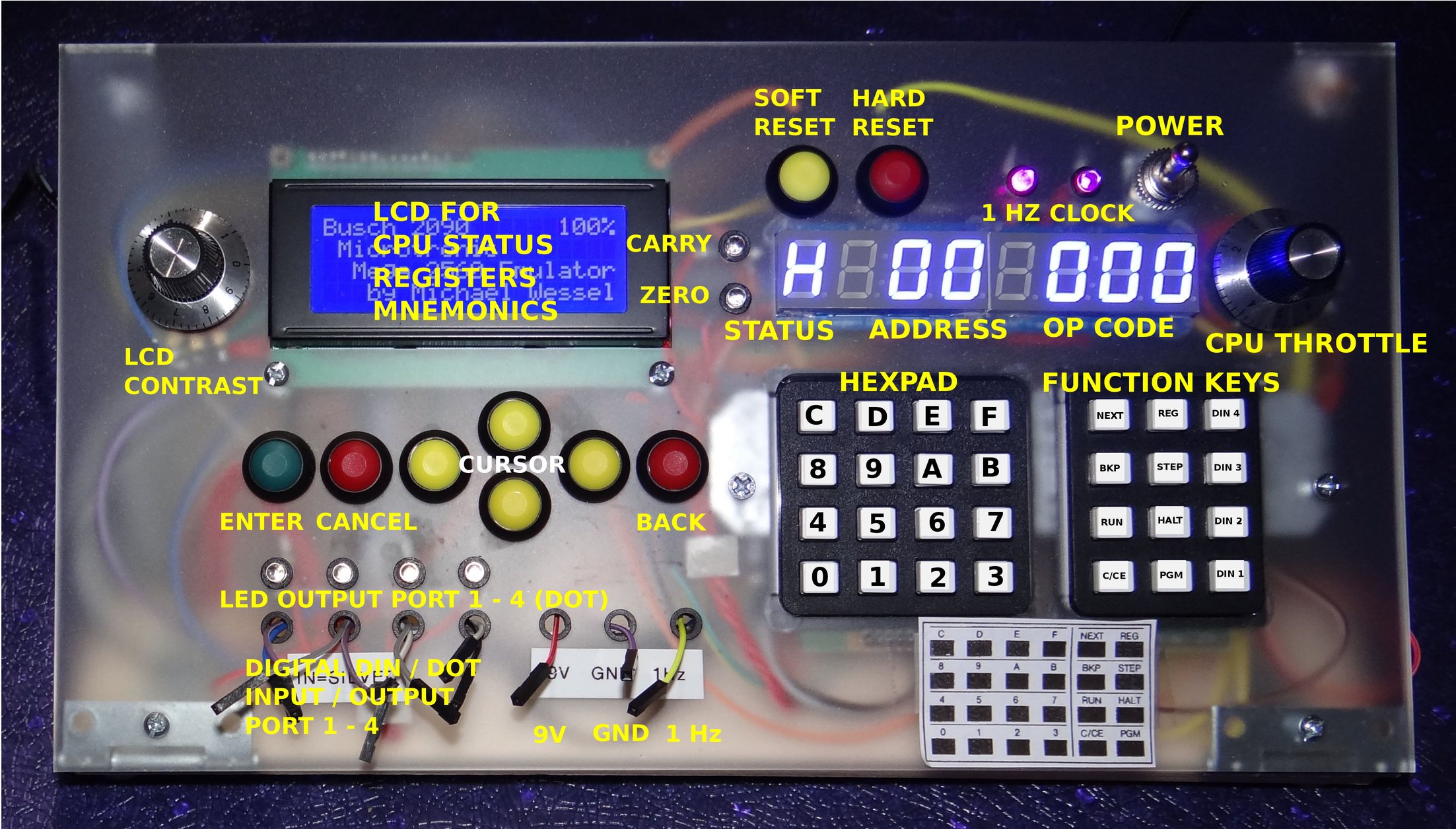
Explanation of Front Panel

Some YouTube Videos

Description of the Microtronic, its CPU and Machine Language

I was asked to provide some more details about the Microtronic and its machine language. Here we go:

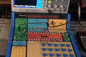
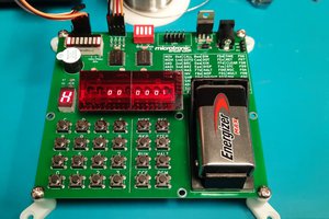
The Microtronic is a very simple computer. It is programmed in a custom machine language, called 2090 ML in the following. 2090 ML is a virtual machine language, interpreted by the monitor program / operating system of the Microtronic. The original Microtronic uses a TI TMS 1600 Microcontroller, clocked at 500 kHz, and executes 2090 ML at a speed of a couple of 2090 ML instructions per second. This Microtronic Emulator runs on an Arduino Mega 2560, and the interpreter and operating system / monitor program was "reengineered" in C (I don't have the original TMS 1600 machine code of the operating system / monitor program). The emulator achieves a higher speed than the original Microtronic, but it can be throttled down with a pot.

The Microtronic program memory has 256 words of 12 bits. It has two sets of 16 universal 4 bit wide registers, 0 - F. There are instructions to swap / exchange the work and aux register sets. The CPU has Carry and Zero flags, and offers conditional and unconditional branching, as well as subroutines. The original Microtronic disallowed subroutine calls from subroutines due to the lack of a stack for storing the program counter, but my emulator allows nested subroutine calls (and the stack size is adjustable).

The 2090 ML was designed under didactic and pedagogic considerations, offering high-level instructions for otherwise tedious (or impossible) to implement operations, e.g., decimal multiplication and division, hexadecimal to decimal conversion (and vice versa), real time clock, random generator, display output, etc. The program memory is read only; the only write able memory is register memory. In a sense, the Microtronic implements a Harvard Architecture, with the only (write able) data memory being the register memory.

With regard to IO, there are instructions for displaying register content on the 6digit 7segment display. There is 4 bit wide digital input, and a 4 bit wide output port. Also, there is an instruction that waits for input from the hexadecimal keypad and stores it into a register.

A Simple Microtronic Example Program

To give a first example for 2090 ML, a simple digital 4bit counter on the LED 7segment as well as the 4 digital output LEDs looks as follows:

Address Mnemonics OP   Comment
===========================================================
00      MOVI 00   100   Load 0 into register 0
01      DISP 10   F10   Display 1 register, starting at 0 
02      ADDI 10   510   Add 1 to register 0
03      DOT  0    FE0   Bring register 0 to output port
04      GOTO 02   C01   Goto address 01

The Microtronic Instruction Set

In the following, the 2090 ML instruction set is listed. I use the following notation: s = source register (0-F), d = destination register (0-F), n = 4 bit immediate constant (0 - F), and aa = 8 bit address (00 - FF). reg(d) denotes the content of register d (0 - F). The aux registers are denoted by 0' - F'. Unless indicated otherwise, flags don't change. "... -> d" means copy ... into register d. I am using standard C operators, i.e. "&" is bitwise AND, "|" is bitwise OR, then there are left and right shift operations ">>" and "<<" An "I" suffix to the Mnemonics means "immediate", and "iff" means "if and only if".

Two address instructions:

MOV   = 0sd : reg(s) -> d.
        Zero if reg(d) = 0.

MOVI  = 1nd : n -> d.
        Zero if reg(d) = 0.

AND   = 2sd : reg(s) & reg(d) -> d
        Carry = false. Zero iff reg(d) = 0.

ANDI  = 3nd : n & reg(d) -> d.
        Carry = false. Zero iff reg(d) = 0.

ADD   = 4sd : reg(s) + reg(d) -> d.
        Carry iff overflow. Zero iff reg(d) = 0.

ADDI  = 5nd  n + reg(d) -> d.         
        Carry iff overflow. Zero iff reg(d) = 0.

SUB   = 6sd : reg(d) - reg(s) -> d.
        Carry iff underflow. Zero iff reg(d) = 0.

SUBI  = 7nd : reg(d) - n -> d.
 Carry iff underflow. Zero iff reg(d)...
Read more »

TERMINAL.MIC

A terminal program for sending text / ASCII characters from the Microtronic to the Uno-based Emic 2 receiver.

mic - 523.00 bytes - 05/28/2016 at 14:48

Download

schematics-microtronic-emulator-color.pdf

Schematics of Microtronic Mega Emulator / Color. Created with KiCad. Please appologize any rookie mistakes - that's my first schematic ever.

Adobe Portable Document Format - 147.78 kB - 05/15/2016 at 05:29

Preview
Download

schematics-microtronic-emulator-bw.pdf

Schematics of Microtronic Mega Emulator / Black and White. Created with KiCad. Please appologize any rookie mistakes - that's my first schematic ever.

Adobe Portable Document Format - 145.30 kB - 05/15/2016 at 05:29

Preview
Download

blueprint.pdf

Blueprint for face plate.

force-download - 36.61 kB - 05/08/2016 at 01:55

Preview
Download

busch-calculator-overlay.jpg

Keypad overlay for calculator program.

JPEG Image - 66.92 kB - 05/08/2016 at 01:55

Preview
Download

View all 8 files

  • 1 × Arduino Mega 2560 R3
  • 1 × 4x4 keypad with matrix encoding for hexadecimal input
  • 1 × 3x4 telephone keypad, for function buttons and DIN input, NOT matrix encoded
  • 8 × LEDs and matching protection resistors (for 5 V)
  • 4 × Pull-down resistors for DIN digital inputs (typical 10 kOhms)

View all 16 components

  • After about ~6 years, it's time for a firmware update!

    Michael Wessel01/17/2022 at 03:28 0 comments

    An updated firmware (January 2022) for the Microtronic Mega Emulator Version 3 from 2016 is available here.

    Like the 2016 version, it supports speech output over the Emic-2 speech synthesizer. Please refer to the 2016 documentation for further details.

    Note the following changes to the 2016 version:

    • PGM programs are no longer stored in EEPROM, but in PROGMEM (hence, ignore all instructions in the 2016 documentation referring to a prior programming of the EEPROM, this is not necessary any longer).
    • The 1 Hz clock signal is now properly implemented by means of a timer ISR.
    • Speech output can be en/dis-abled. Default is off.
    • Some bugfixes to the CPU emulation (e.g., SHR).
    • HAL9000 quotes and Magic 8 Ball speech functions disabled.
    • CPU throttling is now non-blocking, e.g., delay is not used in order to not slow down reactivity of the emulator.
    • Increased speed.
    • Code refactoring.

    This compiled with the Arduino IDE Version 1.8.15 in January 2022.

  • The Future

    Michael Wessel05/28/2016 at 05:48 0 comments

    What could be next steps for this project? I am planning to make a PCB for the project. I am learning KiCad and started work on the schematics. A first version of the schematics can be found in the files section of this project. I am not sure how to add the Mega 2560 and SDCard shield functionality to the PCB though. Also the Emic 2 will have to stay separate, right? It will be a good learning project for me.

  • Phase Seven - The Talking Microtronic Emulator - Mega Version 3

    Michael Wessel05/27/2016 at 13:35 0 comments

    I liked the Emic 2 so much that I decided to buy a second one, and this one was going to be installed permanently, making the emulator speak all the time. I found two more unused IO pins that would work with the software serial library (not all pins support the required change interrupt), and mounted the Emic 2 to the base board. I purchased a (passive) ham radio speaker; the Emic 2 has an internal amplifier which is powerful enough to drive a passive speaker. The sound was loud and clear.

    The inclusion of the software serial library into the Arduino sketch plus many more strings for the utterances of the Emic 2 now caused some major headaches. Suddenly, with the Emic 2 being part of the setup and all these strings being created dynamically using the String library, the file IO operations and LCD shield were no longer working properly. One effect was that the file bowser crashed, showing random characters on the LCD. Only a hard reset would resurrect the emulator then.

    After a lot of debugging and trial and error I found a major culprit - the String library, and the SDCard library using the String library internally. Since there are neither destructors nor Garbage Collection, it seems that dynamically created strings are causing memory leaks, and at some point, the Arduino simply runs out of SRAM. I had to bite the bullet and removed the String library completely from my code, using character arrays / buffers instead. In addition, I replaced the SDCard library with the SdFat library. That solved all my stability issues, but it required some major code revisions.

    The built in Emic 2 now confirms every keypress and function key, and the cursor keys - when not being used for file operations - trigger the following Emic 2 operations:

    • Left : describe current system status
    • Right : describe content of 7segment display and of the 4 digital outputs
    • Up : general Microtronic emulator information
    • Down : emulator software version
    • Cancel : get an answer from the Magic 8-Ball
    • Back: listen to HAL 9000!

    Also, activities such as loading a PGM or SDCard program, clearing the program memory, and displaying or setting the time, are confirmed and spoken by the Emic 2. The clock program / PGM 4 is turned into a talking clock. While PGM 4 is running, a press on the right cursor key make it speak the current time.

    So, the monitor program / operating system was speaking by now - but of course, I also wanted to program the Emic 2, making it speak arbitrary sentences. The previous setup in Phase Six used the digital outputs of the Microtronic as well as another Arduino Uno as an intelligent receiver buffer and baud converter for the Emic 2. Obviously, it would be much nicer if the Emic 2 could be accessed and programmed directly by means of certain 2090 machine instructions, with no extra hardware nor wiring required. However, there are no unused OP codes in the Microtronic which could be used for that purpose (all OP codes from 000 – FFF have a meaning!) So, I couldn’t just invent a new OP code for accessing the Emic 2. But wait - there are redundant op codes. The effect of a MOV xx = 0xx instruction is to copy the contents of register x onto itself, so these instructions are basically vacuous, and no real Microtronic program is using them for anything. I hence gave them an extra meaning / extra effect – in addition, a MOV xx also sends a (high- or low) nibble x to the Emic 2. A full ASCII character with decimal code xyz (e.g., 120 = xyz for character “x”) is thus sent via instructions 0ww, 0zz, where w is hexadecimal for xy - note that xy <= 12 (ASCII goes from 0 to 127), and hence w can take hex values from 0 to C. This decimal-based hex coding is used in order to make the entry of ASCII character codes more convenient. In order to speak a sentence, the Emic requires a heading “S” as well, and then a trailing CR (ASCII code 13). To make the Emic 2 thus speak “xyz” ("ex why zee") it takes the program “088...

    Read more »

  • Phase Six - Emic 2 TTS Module for Microtronic & Emulator

    Michael Wessel05/27/2016 at 13:29 0 comments

    I have always been fascinated with speech synthesis - I guess a good dose of SciFi movies in my childhood nurtured this fascination, from "Colossus - The Forbin Project", over HAL 9000 in "2001" and "2010", to "Proteus 5". In 1984, when I got my original Microtronic, a page in the Microtronic Manuals announced that a speech module for the Microtronic was under development, and that it would be available soon (the manuals were printed in 1981). Well, that never happened. 35 years after this announcement, I decided it was time to make this promise true, and finally have a speaking Microtronic Computer System - I hence ordered the Emic 2 TTS module, and started tinkering with it. Programming it over the software serial port from an Arduino turned out to be really easy. All it required were two digital pins, on for RX and one for TX, and the software serial library at 19.200 baud.

    However, it was more challenging to actually connect it to the Emulator or even the original Microtronic. The Microtronic only has 4 digital outputs, and can achieve something in range of a couple of bauds (perhaps 5 to 10?). I was investigating how to increase the baud rate using UARTS and similar devices, buffers and shift registers, but it turned out to be too complicated. Notice that the baud rate has to be accurate within 10%, otherwise the Emic 2 will not receive anything, and the Emic 2 can not go slower than 19.200 baud. It turned out that the simplest solution was to use another Arduino Uno as an intelligent "buffer" and baud converter. The Uno would listen to the 4 digital outputs of the Microtronic and act as a receiver / input buffer. When ready, it would flush the buffer at 19.200 baud over software serial to the Emic 2, making it speak.

    Listening to the 4 digital outputs of the Microtronic (and of the Emulator as well) turned out to be difficult, too. First, I had to "invent" a data transmission protocol which would be timing independent and hence more robust - I needed a "self clocked" data transmission protocol, without any start or stop bits, which would also not require a fixed baud rate. I decided to use the zero as a clock signal in the data stream - in order to then transmit zeros in the data stream, I simply added +1 to all data nibbles. That way, a zero always means "wait for the next nibble". The second challenge was that even with data transmission rates as low as a couple of bauds, the digital inputs of the Arduino were somehow too slow and I couldn't get reliable readings. I was using a 4bit counter as a test, and received values such as 0, 1, 3, 2, 3, 5, 4, ... I tried reading directly from the PORTB register of the ATMega, instead of using the Arduino IO. This solved the speed problem (reading is much faster then!), but still the read values were shaky. I could only overcome this problem by using the Arduino's analog inputs, and setting analog-to-digital conversion thresholds manually.

    Finally, it worked with the emulator, and a little bit later also with the original Microtronic! The Microtronic could finally speak. The sketch for this Emic 2 Uno buffer is on the Github page as well. There is one version for the emulator, and another one for the original Microtronic. But version are shown in the videos below. The small Microtronic program memory cannot hold Emic 2 messages longer than 58 characters. Each character requires at least three machine code instructions (two instructions for loading the upper and lower nibbles of the ASCII character into appropriate registers, followed by a subroutine call which does the +1 conversion, and then sends the two nibbles over the wire to the Emic Arduino, interleaving it with zeros for clocking). Two more subroutines are required for initializing the Emic, and one for sending a CR, causing the Uno to flush its input buffer to the Emic 2, which makes it speak. After all this, there is only program memory left for 58 characters.

    I have also coded a simple terminal program for the Emic 2....

    Read more »

  • Phase Five - Digital Inputs & Connecting Busch Electronic Kits

    Michael Wessel05/27/2016 at 13:27 0 comments

    Next I was trying to connect some simple Electronic circuits from the Microtronic Manuals to the emulator, using the original Busch Electronic Kits. I had built the transistor-based sound oscillator and when I connected it to the Arduino, there were some leakage currents. I hence added for signal diodes such that current can only flow "out" of the outputs, and not back in and through to another output.

    For another experiments, I needed the four digital inputs of the Microtronic. The experiments from the Busch Manuals require the input levels to be roughly TTL compatible. I experimented with various pin modes on the Arduino, including INPUT_PULLUP, and INPUT, and figured that the inputs will only work correctly and reliably if I added external pulldown resistors and used INPUT pin mode.

    So, the outputs required 4 signal diodes to prevent leakage currents, and the inputs required external pulldown resistors. This also had the nice effect that the inputs would correspond to non-inverted TTL levels, and the circuits from the Manuals worked. I soldered the signal diodes and pulldown resistors on two little perboards and mounted them on the base board (notice that the Arduino only has pullup resistors build in).

    This step is documented here:

  • Phase Four - Mega Version 2 with Cabinet and Front Panel

    Michael Wessel05/27/2016 at 13:26 0 comments

    I decided I wanted a good looking, fancy front panel for my Microtronic emulator. I designed a front panel blue print and tried to cut it out from plywood. I even acquired a used scroll saw, but I was unhappy with the result. I decided I wanted a more professional looking front panel, and was excited when I found the Custom Laser Cutting Service offered by Pololu Robitics and Electronics. All they required was the blueprint as a PDF, and 6 days later I had my transparent acrylic iced, fantastic looking front panel in the mail.

    I mounted the big 20x4 LCD white-on-blue display as well as the two blue 7segment I2C-based LED backpacks (each with 4 digits) from Adafruit, and the 4x4 keypad. Since I was no longer using the LCD+keypad shield and had also lost the additional 8 buttons from the TM1638, I needed a lot of discrete N.O. pushbuttons, as well as LEDs (blue of course), and another 3x4 keypad for the function buttons.

    Turns out that I would be using most of the Mega's IO pins now for wiring up all the buttons, LEDs, keypads, etc. An additional 4 pins were needed for the Microtronic's digital inputs, one more output pin for the 1 Hz clock signal, and so on. In the end, not many ports were left.

    After I had wired up the front panel hardware, I simply used a wooden base board of matching dimensions, and hinges and L-brackets from Osh to create the triangular case you are seeing on these pages. The Arduino is mounted on the base board using screws. Hotglue was my friend, too. The case is easy to open up and this is still the only way to gain access to the SDCard in the SDCard+Ethernet shield (Ethernet is not used for anything currently btw).

    The software had to revised significantly - after all, most of the hardware had changed, the only constant being the Mega 2560, the keypad, and some buttons. In order to drive two Adafruit LED backpacks of I2C I learned that the address of one of those had to be changed, by soldering a jumper. I also learned how to wire up the contrast potentiometer for the 4x2 Hitachi HD44780 LCD display. The contrast potentiometer was part of the LCD+keypad shield in the previous version, which I was no longer using.

    Finally, Version 2 was working! At the end of Phase 2, Mega Emulator Version 2 looked as follows:

  • Phase Three - Connecting Circuits to Microtronic's Digital Outputs

    Michael Wessel05/27/2016 at 13:18 0 comments

    All these additional IO ports on the Mega 25650 couldn't be left unused! So I used 4 digital outputs of the Mega 2560 as Microtronicdigital outputs, and made some experiments connecting simple circuits to them. For example, I built a 555-based tone generator using a simple resistor ladder that created some crazy sounds.

    Then I began thinking about a cabinet for the project....

  • Phase Two - Mega 2560, SDCard, LCD Shield

    Michael Wessel05/27/2016 at 13:14 0 comments

    When the Arduino Mega version arrived I added an SDCard+Ethernet Shield to it, as well as an LCD+Keypad shield (a standard Hitachi HD44780 LCD plus 6 push buttons). The LCD shield was required for operating the SDCard interface, e.g., browsing through files for PGM 1 (Load) and creating new files via PGM 2 (Save). It turned out that they didn't quite work together -I had to disconnect PIN 10 (I used extension headers and simply bent PIN 10 out of the way such that the LCD shield did not connect to it). I implemented the file operations using the String library and SDCard library. These two choices in libraries would cause major headaches later... see below.

    The 6 push buttons on the shield were used for enter, cancel, and cursor movement. In addition, the 8 push buttons on the TM1638 were still being used for the Microtronic function keys.

    I came up with the .MIC fileformat described in the Detail section above, and used an OCR program to scan programs from the Busch Microtronic Manuals. Suddenly, I had a large software library, with relatively little effort!

    Running some larger programs I spotted some errors in the implementation of some instruction code - after all, I had reimplemented the virtual CPU based on the descriptions in the manuals, and the descriptions were incomplete and missleading in some cases (but only in 4). After a while of debugging I was able to run even the largest programs without differences from the documented behavior.

    I figured it would be a shame to only use the LCD display for file operations, and hence implemented a CPU status display, showing register contents and a simple Mnemonics display during program editing etc. Very helpful for debugging.

    The state of the emulator after Phase Two is represented by these videos:

  • Phase One - Uno R3, TM1638, 4x4 Keypad Matrix

    Michael Wessel05/27/2016 at 05:08 0 comments

    This project is basically done, but here are some log entries in retrospect, highlighting some construction issues and how solved them.

    I started this project with an Arduino Uno R3, a 4x4 matrix encoded keypad, and a TM1638 module equipped with 8 7segment digits, 8 push buttons, and 8 LEDs. This was enough for a first version. The 8 push buttons of the TM1638 module were used for the function keys of the Microtronic, 4 LEDs for the digital outputs 1 to 4, a carry, zero, and 1 Hz LED flag. The nice thing about this setup was that it is basically a software project - only the keypad needs to be wired up. For a software person such as me this was a perfect starting point!

    Examples PGM / ROM programs were stored in the EEPROM of the R3. It had difficulties storing longer PGM ROM example programs in the Uno, though. For example, the Lunar Lander program needs over 140 instructions. In my first attempt, I tried to store PGM ROM programs as

    const char *string_table[] = { "F10 510 C00", ... }
    and programs were stored as HEX strings as shown. Unfortunately, the monitor program already consumed a lot of SRAM for static and dynamic variables, and I got compiler warnings regarding potential stability issues.And indeed, the Microtronic emulator was not running stable and showed erratic behavior. The next idea was to store those program strings inPROGMEM memory. In principle a good idea, but in order to retrieve these strings back, a string buffer (in SRAM) large enough to hold the longest program string is required, and I was out of SRAM again. Hmm. Then I tried storing the PGM ROM programs in EEPROM, byte by byte (not as hex strings), but for some reason, I still encountered erratic behavior with large programs such as Lunar Lander. I hence decided to move to the Arduino Mega 2560. Where the Uno has 32k Bytes of Flash, 2k Bytes of SRAM, and 1k Byte of EEPROM, the Mega 2560 comes with 256k Bytes of Flash, 8k Bytes of SRAM, and 4k Bytes of EEPROM. That should be more than enough!

    The tight memory on the Uno also prevented adding much needed features, such as the SDCard shield for storing and loading programs from SDCard, given that these shields and required libraries needed some memory, too.

    Even though I couldn't store larger ROM example programs with this setup, the emulator was functional enough to enter longer programs such as the Lunar Lander by hand, and then play them, but there was no way to save the program. I continued to develop the Uno Version until my Mega 2560 arrived. I also added some buttons to the breadboard, such as a soft-reset (as the Uno's hard reset clears the program memory of the emulator), the CPU throttle pot, and the Microtronic's 4 digital outputs.

    The state of the emulator after Phase One is represented by this video:

  • Microtronic Emulator Blog

    Michael Wessel05/03/2016 at 19:44 0 comments

    The project log can be found here.

View all 10 project logs

View all 6 instructions

Enjoy this project?

Share

Discussions

kc8kva wrote 07/19/2021 at 14:46 point

I got my digital start with a Fisherteknik Microprocessor kit which used the peg and wire system.  I am so going to try this out as it brings back memories of the systems that brought me up to who I am now.  Vielendank!

  Are you sure? yes | no

Michael Wessel wrote 07/19/2021 at 21:14 point

Oh that's interesting, I also had Fischertechnik, before I got my first Busch kit in 1981. I wasn't aware of a Microprocessor kit from Fischer though. I know that they later offered Interfaces to the C64 and Amstrad CPC etc., for Fischertechnik Robotics. So one could build a "Towers of Hanoi" robot with electromagnets and motors using Fischertechnik, and control it from the C64 or CPC. So it seem they also had some (later?) Microprocesser controller kits? I have to research that, any links appreciated!

Good luck with the project! The most recent version (and probably easiest to assemble) is this one though; this only requires standard components (Arduino R3, LED&Key etc.):

https://github.com/lambdamikel/Busch-2090#the-2021-arduino-uno-r3-version

Thanks and good success! Let me know if you run into issues.

Cheers,

Michael

  Are you sure? yes | no

zpekic wrote 12/23/2020 at 13:30 point

Congrats for amazing job with such well documented and interesting project! I am interested in FPGA recreations of old processors, and TMS1600 seems similar to TMS0800 which could also be changed with mask programming (e.g. different machine instruction sets to support different calculators). Is there any documentation for the processor and the mask used for Microtronic?

  Are you sure? yes | no

Michael Wessel wrote 12/23/2020 at 16:14 point

Thank you Zpekic - please note that my current version is this one though:

https://hackaday.io/project/176466-microtronic-the-next-generation

The "Next Generation" has a number of more advanced features and also less bugs ;-) 

I am afraid the masks and monitor program ROM code is not available... I tried to reach out to Busch about this, but to no avail. The TMS 1600 documentation is available of course: 

https://en.wikichip.org/w/images/f/ff/TMS1000_Series_Programmer%27s_reference_manual.pdf

Cheers and happy 2021, take care and stay safe

Michael

  Are you sure? yes | no

zpekic wrote 12/23/2020 at 22:06 point

Hi, thanks for the pointer, I will definitely check it out! Too bad it is not available, it would be interesting to see how that level of coding was done, usually they are full of clever tricks one can learn from. But with a sufficiently well documented instruction set, a processor can be implemented that may be internally different but functionally the same.

  Are you sure? yes | no

Michael Wessel wrote 05/04/2016 at 16:15 point

Thanks Alain :-) 

  Are you sure? yes | no

Alain Mauer wrote 05/04/2016 at 11:12 point

Nice setup

  Are you sure? yes | no

Similar Projects

Does this project spark your interest?

Become a member to follow this project and never miss any updates