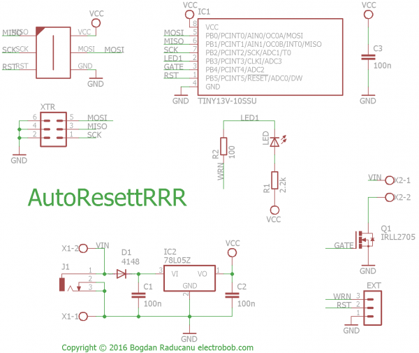
I finished the board and sent it to the fab. Schematic and PCB rendering below. Files are available at GitHub. The usual 5V regulator with fool proof diode ensures a good 5V supply for the ATTiny13 micro, up to 35V input. There are no worries for powering the device from 5V directly, at the low current consumption it will get about 4V, enough for proper operation. But of course, you can totally skip the regulator in case of a 5V supply. A IRLL2705 logic level NMOS takes care of switching the load. And the brain is a small 1k of flash micro, the ATTiny13.
Your typical LED insures a nice blinky to tell you everything is working. The same output is going to intelligent loads like the Raspberry Pi: 2 minutes before the reset the LED will stay constantly on, to tell it to shut down. The same pin is used bidirectionally: if the load will pull it to ground, that is a sign that it should be powered off soon, so the AutoResetRRR will cut the power after a delay.
 electrobob

Discussions
Become a Hackaday.io Member
Create an account to leave a comment. Already have an account? Log In.