 sidsingh
5/15/14: These OLED displays seems to be part of the button deck and they will look great on any project. Also, the OLED Screen is surrounded by 8 RGB LEDs.
I love displays and OLEDs are such a beauty because they have very wide viewing angle and superb contrast and resolution. I don't even know if they work or will work! but I got excited when I saw microchip PIC18F67J10 on the PCB driving these puppies. I can't wait to test them, but before that I have to reverse engineer the PCB traces, connections and find datasheets.
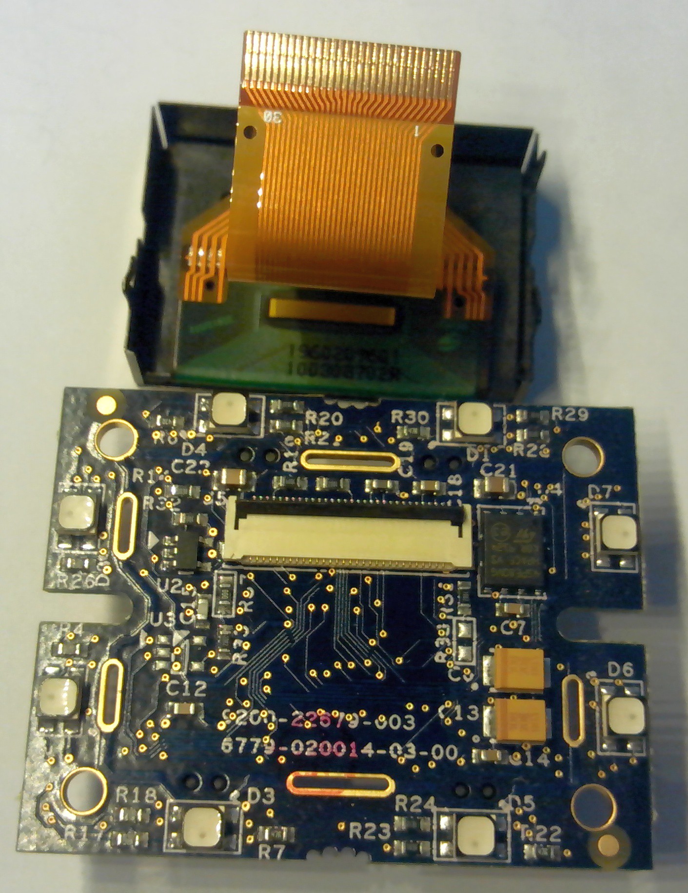
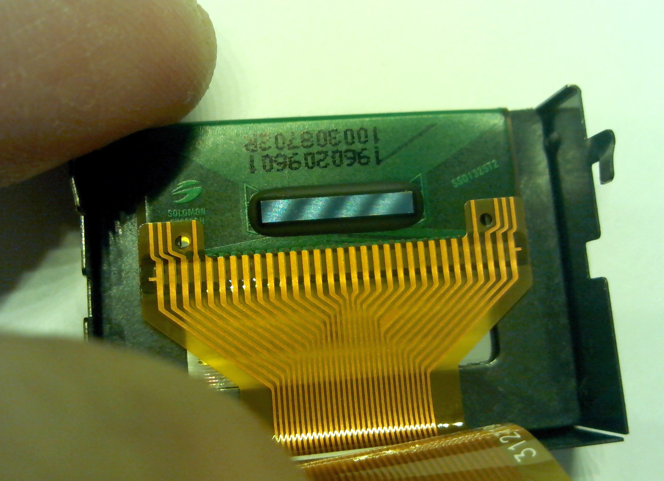
I took apart the OLED display and the PCB, it was easy. Display is connected to PCB with a 30 pin flat flex cable, and the PCB's underside has 4 groups of connectors for programming and data to the PIC. A closer look at the display and the manufacturer is "Solomon Systech" and OLED controller is "SSD1325T2". A quick visit to the Solomon Systech website did not reveal much and to get a datasheet you have to place a request, which I did (hoping they will respond). After googling for few minutes, I found SSD1325 is a 128 x 80, 16 Gray Scale Dot Matrix LED/PLED Segment/Common Driver with Controller.... which means every single pixel will light up in 16 shades ... great for displaying bitmaps and graphics Yaaay :D !!! (will try to find datasheet later)
Overall the PCB does not look overly complex and I truly hope it to be double sided. It will be a nightmare if this turns out to be a multi-layered PCB! The traces and vias are very thin and small, so I am looking at hours of effort under a lens and a probe.
Components on the PCB:
On the bottom side of PCB, I do not see many components. 64 pin TQFP PIC18F67J10 is running the show, a 10MHz crystal, bunch of resistors and caps. Few 3 legged SOT23s, IR LEDs and IR detector. IR stuff is placed around a slot on PCB, so I am guessing this module is also used as a button and whenever depressed, something moves in or out of that slot interrupting the IR beam. There are also four groups of PCB connectors on the bottom side, One of them could be ICSP and data in/out for OLED and power supply.
On top surface of the PCB there are eight RGB Leds (two on each side). I do not see any other chips which could be used to multiplex these LEDs, so I am assuming these LEDs are directly driven by individual uC pins. There is also a 1MB (8Mbits) Serial Flash Memory 45PE80VG. Not sure what that is used for, but the PIC18F67J10 is a fairly loaded chip with 128K of Program memory and 4KB of RAM. A quick look at serial flash 45PE80VG datasheet reveals it is a SPI bus Flash. There is a 30 Pin FFC connector for display. Other than these, I do not see anything of interest on the top layer.
Next steps:
Figure out the traces on PCB and hunt for SSD1325 datasheet and pinout of FFC. I will start probing PCB in a day or two and will keep posting my progress.


 Saul
Saul
 Clint Stevenson
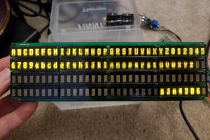
 sjm4306
 Moritz v. Sivers
what happened with the oled button project