Close
0%
0%

ODrive - High performance motor control

Hobby brushless motors are incredibly cheap and powerful. However we need a way to make robots out of them. ODrive is that way.

Similar projects worth following
Stepper motors are ubiquitous in hobby robotics projects: If you make a robotics or automation project today, it is very likely you will use them. Almost all DIY projects from 3D printers and CNC mills, to air hockey and juggling robots use them. However in industrial automation, brushless servomotors have taken over, and it's clear why: They don't lose steps, are much more powerful, efficient, and silent.

However, brushless motors are not unique to expensive industrial automation equipment. In fact, you can get some very powerful and cheap motors at hobby shops. The electronics to drive these motors are also dirt cheap. So how come virtually no non-industrial automation systems use them?

To be honest, I have no idea. Seriously, a driver that allows this should clearly exist.
But since it didn't, I decided to make one.

And you are invited!
This project is open source, both in hardware and software, and I warmly welcome anyone who wants to join.

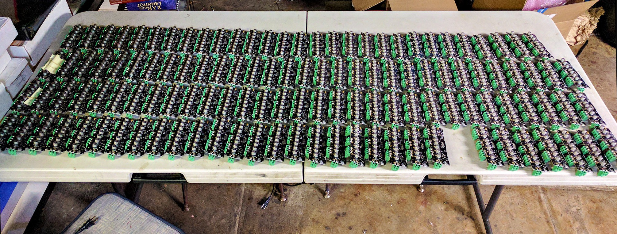
Boards are available

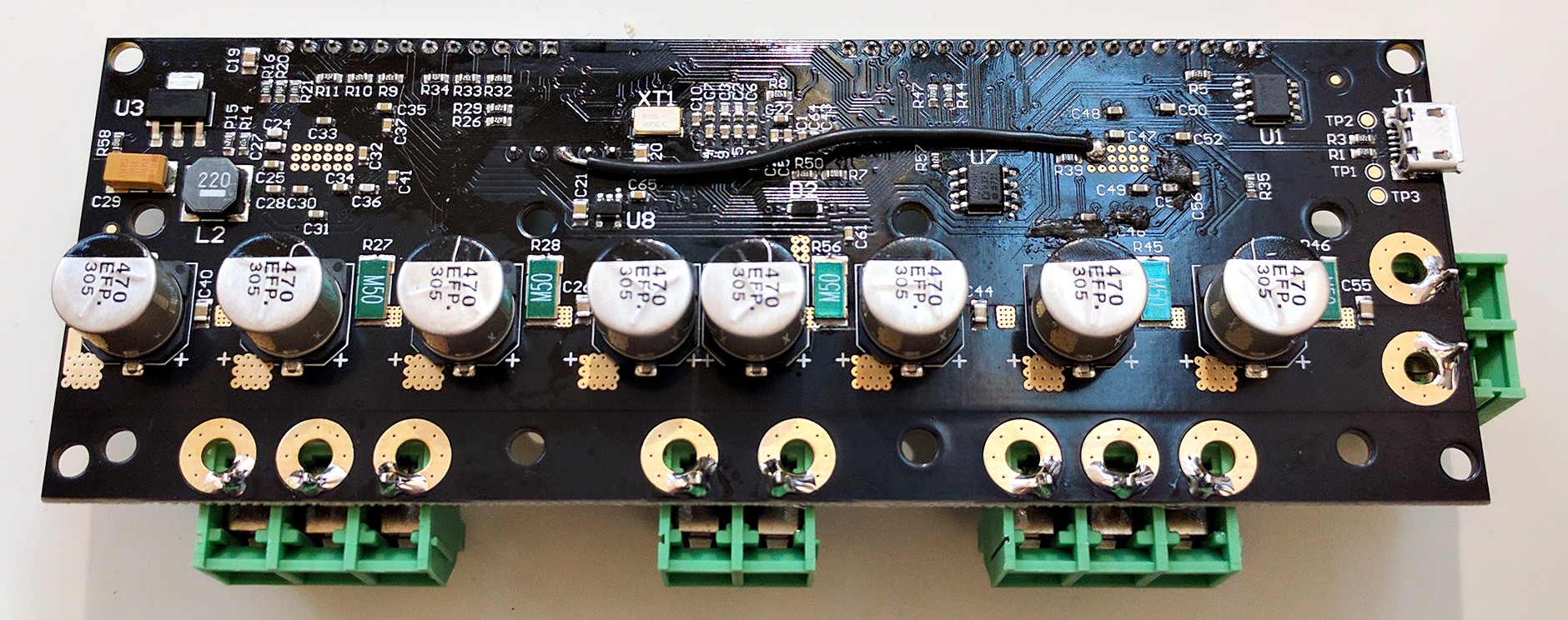
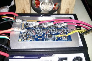
ODrive v3.5 boards are available at the ODrive Shop.

Key specs:

  • 2 motor channels, designed for >100A peak current.
  • 1 DC-DC converter channel
    • For powering the system with an arbitrary voltage power supply, or
    • Use of a brake resistor
  • 24V bus voltage
  • USB, CAN, UART, PWM, and step/dir interface (read more below)
  • Encoder feedback for arbitrarily precise movements
  • Supports power regeneration
  • Use of a high power density Li-Po battery means you can achieve >1kW peak power output with only a modest power supply.
  • It will feature various optimal control strategies and motion profiles.
  • Permissive licence on both hardware and software: You use this project in anything you like, even commercial products (as long as you attribute this project's contributors).

Demos

The design is based on two earlier prototypes.

Here are some very simple demos with v2. The peak power output in these tests were only about 60W. The new version (v3) will be able to deliver much more power.

Below is a demo with v1. The mass being moved is 3kg, and the peak power was about 200W. The noise is not from the motor, but from my poor mechanical design which means that the belt teeth rubs against the idler pulley edge.


Join the discussion!

Check out the ODrive Community.

Stay up to date


Motors

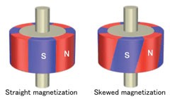
Check out the ODrive motor guide. You can also read this post about outrunner motors.

Interfaces

  • USB Serial port -- PC, BeagleBone, RaspberryPi, etc.
  • CAN -- CANOpen and CiA 402 is a possibility
  • UART -- Arduino, mBed, etc.
  • PWM -- RC Recievers, Arduino, etc.
  • Step/direction -- Existing motion controllers
  • Some general purpose digital and analogue pins

Protocols

  • G-code parser for interfacing with existing automation tools
  • Many types of command modes
    • Goto (position control with trajectory planning)
    • Position commands
    • Velocity command
    • Torque command

Architecture


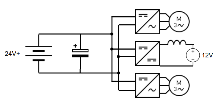
The drive is designed to be able to deliver incredibly high peak power, more than 1kW per motor channel. However, power supplies that can deliver this kind of power are expensive. Also, when the actuator is being decelerated, there is energy absorbed. Most power supplies do not like having energy dumped back into them.

The solution: Put high-power energy-storage on the DC bus. A battery like this one can deliver around 3kW. These types of batteries also have a fairly high charge rating, and if the regeneration is only over a couple of 100 milliseconds, they can probably handle a fair bit more than specified. Thus, they should be able to handle the full range of regeneration power in most robotics applications.

This means we have a variable voltage DC bus, that fluctuates with the battery's state of charge. So the way we power the system is via a DC-DC converter. There is another upside to this as well: we can use any voltage power supply and just convert it to the bus voltage. I expect most people will use an inexpensive ATX power supply (specifically the 12V rails). In many robotics applications the motion consists of several discrete movements, only some of which are high power. In this case, we can have access to a very high peak power, but only require a very modest power supply.

Another thing that's nice about using a battery for stabilising the DC bus, is that if multiple of these drives reside on the same bus, there is no fighting over the regulation of the bus voltage: a single board can have the DC-DC connected to a PSU, and the rest of the boards in the system can just use the bus. If fact, you can even skip populating the DC-DC on the slave boards.

The system is also capable of using a brake resistor to dump the regenerated energy instead of a battery to absorb it. This is a simpler and possibly safer setup, and is also what the project will use in the first instance, until the battery storage feature is ready.

Applications

So this project is good for some things,...

Read more »

  • 2018 in Review and New EU Webshop Open

    Oskar Weigl12/30/2018 at 06:11 3 comments

    Many of our European customers will be happy to know that the EU webshop is now officially open. Most of our products are now stocked and available from a warehouse in the UK. The shipping times to Europe should be drastically improved when ordering from there.


    Now that we have reached the end of the year, I want to take the opportunity to summarise some of the highlights of the past year, and to thank each and everyone of you for the incredible support we've received.

    In the beginning of 2018 we released ODrive v3.5, and with that we reached a stable hardware version. With that we were able to focus our efforts on improving the firmware, supporting software and the overall user experience.

    We saw over 100 new features, improvements and fixes (full details in the Changelog). Just to lift out some highlights, we have implemented:

    • Trapezoidal trajectory planner
    • Switching frequency increased to 24kHz for silent operation
    • Storing of configuration parameters to Non Volatile Memory
    • Many encoder related improvements, including index pulse encoders and Hall sensor feedback
    • RC PWM input

    On top of this there are currently many excellent features waiting in Pull Requests which will be our priority to merge as soon as possible.

    We love seeing so many fantastic projects come to life with the help of ODrive. Check out the Projects category on our forum to see all the ones people have chosen to share. I want to highlight two projects that I found to be particularly excellent.

    The first one is a modular, heavy duty Swiss mill-turn machining center for cutting metal called SwissMak, which uses ODrive to precisely control the two spindles, and will also use ODrive for the movement axes in a future version. They successfully completed a kickstarter, and the first set of machines are being manufactured at this very moment.

    front iso view 2 jan 17

    The other project I want to feature is the Stanford Doggo, a quadruped robot made by a group of students at Stanford University. Check out more photos, and watch it walk, dance and jump extremely high in their excellent video presentation here.

    Stanford Doggo

    To all businesses and hobbyists alike that have chosen to use ODrive; a huge thanks to everyone that have helped to make this possible.

    On top of that we want to specially thank all the direct contributors to the project. For your code contributions, test data, documentation improvements and for providing help to other users on our forum and Discord. Thank you so much, your contributions are invaluable.

    In 2018 ODrive went from a promising project to a successful product and business. We hope to continue on this trend and make ODrive even better.

  • Jan 2018

    Oskar Weigl01/15/2018 at 09:49 0 comments

    Robot Arm and More

    The ODrive project has been very fortunate to attract such a strong community of enthusiasts. Today we want to feature the excellent work done by Richard Parsons, who's been very active on the ODrive Community. In the video below he demonstrates his direct-drive robot arm, how he built and wired up the servo axes, his step/dir tests and finally his high speed pen plotter.

    ODrive v3.4

    Since the last newsletter update, ODrive v3.4 has become available. From a user-perspective, not much of the design has changed from v3.3. However, we now have a 48V version available. It has the same current handling capacity as the 24V version, hence it has twice the power. We are talking around 3kW peak power per axis.

    We can't wait until the videos of projects with this kind of power show up!

    New Encoder

    We now stock the CUI AMT102 encoder in the ODrive Shop. This is a compact 8192 counts/rev encoder with index pulse. It comes with a custom 2m shielded cable that matches the pin-out for the ODrive.

    The increased resolution will help with smoother motion and less "hunting" vibration when holding position. Also, in a couple of weeks, when we expect have the index pulse feature finished, it should enable the ODrive to restore the encoder calibration. This means that the encoder calibration only has to run once to commision the drive, and then skipped every run from then on.

    Above is a design by [Wetmelon] on the ODrive Community. It uses the 1.6kW N5065 motor and the aforementioned AMT102 encoder, to make a NEMA23 compliant compact and high performance servomotor. The above prototype is printed in PET-G filament, that has a glass transition temperature of 88C, so despite using a 3D printed part it should be ok for applications that don't run the motors too hot. If you are interested, he also made a design that uses a 10:1 gearbox, check it out.

    Your Project

    If you also have a project that you are working on that uses the ODrive, or even one that could make good use of an ODrive, we'd love if you shared some pictures with us.

  • ODrive v3.4 Ready Soon

    Oskar Weigl11/24/2017 at 01:09 0 comments

    We have managed to sell out of ODrive v3.3, thank you everyone who has shown such support! The batch of ODrive v3.4 are due to arrive in about a week from now, and we hope to have them tested and available to ship in the beginning of December.

    As you might be aware, we used to have a restriction asking you to not order more than two drives at a time. Now we are able to order much bigger batches, so this restriction is lifted: order as many ODrives as you would like. With this batch and going forward, I think we should be able to keep ODrive from going out of stock.

    On that note: If you are an OEM or Distributor, please get in touch, as we now have the capacity to take large orders.

    Thanks to everyone who has helped to make this possible,

    Cheers, 

    Oskar.

  • Announcing 48V ODrive Board

    Oskar Weigl11/06/2017 at 23:05 2 comments

    Many of you have requested that there should be available a 48V version of ODrive. I'm happy to announce that this is expected to become available in the beginning of 2018. To be notified when it will be possible to order, please sign up here: https://goo.gl/forms/EUJP726GsLaBf5YN2.

    Some things to note:

    • The price is expected to be $149.
    • The current handling capacity will not decrease, hence the power handling capacity will in principle be double that of the 24V version.
    • We will keep offering the 24V version at the same price as before: $119

  • Cogging Torque Compensation

    Oskar Weigl11/06/2017 at 22:55 0 comments

    Inexpensive hobby brushless motors are powerful, but they are not built for precision applications. One of the undesirable characteristics of less expensive motors is cogging torque. This is the torque generated by the permanent magnets in the rotor being attracted to the iron in the stator in an unbalanced way.

    In more expensive motors this is avoided by skewing the rotor magnets, as shown below. This balances the reluctance torque across the skew angle, which eliminates most cogging torque.

    Straight and skewed rotor magnets.

    Interestingly, the cogging torque exhibited by the motor is a constant function of the rotor angle. That means that if we can figure out what it is, we can improve the performance by simply compensating for it.

    And that is exactly what we did. Thanks to the implementation of a calibration and compensation algorithm by @Wetmelon on the ODrive forums, we can estimate and cancel the cogging torque.

    Cogging torque map: Current as a function of encoder count. Measured values in blue, fitted values in orange.

    Without and with anticogging, showing rotor position at 25 RPM commanded velocity. Note that the feedback gains were not very stiff for this test.

    Note that the above is just an excerpt of the full writeup, please see that for more detail, and full resolution plots.

    This algorithm is already merged to the devel branch of the ODrive firmware, and after sufficient testing will be available in the next release.

  • UART and Arduino Library

    Oskar Weigl10/18/2017 at 01:43 1 comment

    The UART feature is now ready for testing.

    Many of you have been waiting for the ability to control the ODrive from another microcontroller, and so this feature complements the USB and let's you do exactly that.

    I have also made a first revision of an Arduino library that lets those of you who wish to use Arduino get started quickly. If you don't use Arduino, you can still have a look at the library to see how the communication is implemented, and copy that to your platform.

    The UART feature is currently in a pull request, which means that the documentation on the master branch hasn't updated yet. Please check the documentation on the uart branch instead. Here are some of the important things that are new for UART:

    If you have any problems, or if everything worked perfectly, or anything in-between: please help us with feedback. Once this feature has been confirmed to work for enough people, we will merge it to the devel and hence master branch in the next release.

  • Three Demos

    Oskar Weigl10/02/2017 at 04:09 0 comments

    It's so awesome to see what kind of cool stuff people are doing with the ODrive. Here are 3 demos of fairly different nature. I think they are awesome, I hope you do too!


    Willam Osman put ODrive on a PowerWheels. This video is actually a few months old now, and I probably should have posted it earlier. Anyway, watch that thing do doughnuts:

    The Arduino library and UART communication is under way, a usable release should be ready in a couple of weeks. Check out the first demo:

    Bauerslab posted his awesome Skittle Sorter on the ODrive forum. It's really awesome to see the diverter teleporting around. If you wanna skip to the action, it starts at 6:15.

  • Which voltage in your application?

    Oskar Weigl08/25/2017 at 03:40 0 comments

    It’s good to know what voltage range people want to use ODrive for in their application. Right now the voltage rating is for 24V, but it’s fairly easy to change. There is a current handling penalty to increase it though, so it might be useful to offer two versions. To help us decide between the different options, please answer the poll about what supply voltage would be the most ideal in your application. You may check multiple options if they apply to you.

    Thanks!

    Link to poll

  • Electrical issue discovered

    Oskar Weigl08/13/2017 at 07:57 0 comments

    Thanks to the help from the community, recently we uncovered a hardware bug that affects all ODrives manufactured to date (v3.3 and earlier).

    This bug is described in more detail here, and the fix is described in detail here.

    In short, the bug means that the GND on the GPIO pins and the M1 motor gate driver has significant spikes of electrical noise. This causes glitches on the control signals on the GPIO pins, and motor control glitches on M1.

    If you plan on using M1, it is strongly advised that you apply this fix. You can follow the instructions as linked above. If you do not feel comfortable applying the fix, you can also send the board to me (San Jose, CA, USA), and I will apply the fix for you, free of charge (you pay shipping to me, I pay shipping back to you). If you need help to apply the fix to your board, please email info@odriverobotics.com, and we can arrange it.

    We have already started applying the fix to all the ODrive v3.3's:

    The fix applied to an ODrive v3.3.

    Applying the fix to all the ODrive v3.3.

  • Sensorless Mode

    Oskar Weigl08/04/2017 at 23:50 0 comments

    Quite a few of you have requested sensor-less operation: running the motor without an encoder. This is now a reality:

    Video shows open-loop startup speed-ramp followed by switching to closed loop FOC velocity control.

    The main limitation of this mode is that it's not able to provide precise control at very low speeds (it can however spin up to speed using not-so-precise control). Therefore, this mode is great for applications where the primary operational regime is at speed. So not great for CNC machines or polargraphs, but great for electric skateboards and conveyor belts.

    If you are interested in the technical details, or have an ODrive and want to try this out, please see the Sensorless mode post on the forum for more detail.

View all 32 project logs

Enjoy this project?

Share

Discussions

f4grx wrote 05/24/2016 at 20:41 point

What are the options for the CAN protocol? This part is relevant to my interests.

I found on the SimplexMotion website that the standard is:

"CANopen standard for motor control systems (CiA-301/402)"

Here:

http://www.can-cia.de/can-knowledge/canopen/cia402/

CIA301 is downloadable, but 402 is "members only" :(

Here is a draft: http://overpof.free.fr/schneider/CAN%20&%20CANopen/CANopen/%A9CiA%20CANCANopen%20CD%20V5.1/standard/dsp402.pdf

I think this project has great potential for CNC control. Steppers are very slow and lack torque and precision, even the NEMA 23 models.

Excellent job!

  Are you sure? yes | no

Oskar Weigl wrote 05/25/2016 at 14:21 point

Hey, yeah a few years ago I was working with an ABB MicroFlex e150, using the CiA 402 protocol. I think it would be cool to support it, but I think there are quite a few features that are higher priority. Of course, if you implement it, I would be very happy to merge it in (:

The inital CAN protocol would probably just feature some very simple process data items only, such as desired torque, speed, and position, and with some mode value (torque only, velocity only, position with velocity and torque feed-forward, etc). Initially there probably will not be any support for configuration over CAN, this would be done over the USB serial.

Again, I'm open to supporting whatever makes sense, if you are willing to write it (:

  Are you sure? yes | no

Marc Peltier wrote 05/24/2016 at 11:59 point

Bravo ! Perfectly targeted, analyzed and specified. Instant 1kw with an ATX power supply, wow!

Can not wait to get one! I already have a ready project that expected it. And dozens of others that come to mind.

I wish you the same success as the Pololu drivers, stepsticks, etc ...

  Are you sure? yes | no

Oskar Weigl wrote 05/25/2016 at 14:13 point

Thanks! ;D

  Are you sure? yes | no

Toon wrote 05/24/2016 at 06:51 point

Great idea.
If you need a alpha tester, let me know. I'm having a little stalled project because of a stepper that can not handle the speed I need. I was going to build something like this myself, but don't have the time to build it.

Why 2 channels? 

If you need some help with building a ui or tool for configuring the board let me know. 

  Are you sure? yes | no

Oskar Weigl wrote 05/25/2016 at 14:12 point

Thanks! Yeah I am looking for developers and alpha testers. I will do just a little more testing to make sure that the current board design is not majorly broken. I am currently having some issues with the programming. When those are resolved, I will do a general outreach for developers and alpha testers, and maybe even do a small batch of machine assembled boards.

The main reason for two motor axes is fairly arbitrary. Due to micro-controller peripheral limitations, the options are basically 1, 2 or 3 channels. I think it would be useful to do a cost estimation for each kind, and do some sort of survey to see what most people prefer.

Yes please!! As soon as I verify that the board works properly, I can help you get hold of one, and then any development effort you can help out with would be fantastic ;D

  Are you sure? yes | no

Toon wrote 05/26/2016 at 08:27 point

Perfect, keep me in the loop. 

Already figured out about the 2 channels. I think a cost estimation is necessary.  
Most CNC's, 3D printers need 3 channels, flatbed router cnc's 4 channels.
I'm even using a Hobbyking NTM_Prop_Drive_50_50_580KV_2000W for my cnc spindle on my refurbished Roland Camm-3 PNC-3000. Would be cool to have a constant speed setting, with stall alarm.

Like someone already said, fan cooling control would be a big plus. Specially on low speed high torque applications. Cooling is mandatory.

Another idea popped in my head yesterday. To make a small board with a RJ45 connect that has the pinout of the pololu stepper that connects to odrive. Doesn't need to be a RJ45 connector. That way you can replace a pololu stepper controller with odrive. 

I'm running TinyG on my cnc, marlin on my 3D printer, grbl on my laserengraver. Soon I'm receiving a smoothieboard for working on a javascript library that can communicate with all these boards: https://github.com/Cinezaster/serialPortJsonClient, for laserweb2 https://github.com/openhardwarecoza/LaserWeb2 a project that is creating a browser based cnc controller and gcode generator. 

I'm all into creating a better, cheaper and easier way for people to have access to machine automation. As I'm looking at odrive, I feel the same philosophy is valid. 

  Are you sure? yes | no

Oskar Weigl wrote 05/27/2016 at 12:31 point

@Toon, Awesome!

On v2 you can interface the board directly with step/dir signals.
I just checked, and unfortunately the pins that are broken out to GPIO on v3.0 are not the correct pins to count step/direction in hardware. It can still be done in software though. On a future board revision we could use a larger pin count package and expose this functionality.

Yes I hope many cool machines and robots will come of this ;D

  Are you sure? yes | no

[deleted]

[this comment has been deleted]

Oskar Weigl wrote 05/25/2016 at 14:01 point

Thanks!

  Are you sure? yes | no

mitja.kumin wrote 05/16/2016 at 10:49 point

Very impressive work! Will there be schematic available? I could do tests with smaller industrial servo motors. There is a realy big potential in this project!

Will it work with quadrature A B encoders? These come realy cheap from china (about 15€ per piece-shipped).

  Are you sure? yes | no

Oskar Weigl wrote 05/16/2016 at 11:06 point

Thanks! The schematic is here https://github.com/madcowswe/ODriveHardware/blob/master/v3/two_ax_PCB.PDF. This is for version 3, which I have yet to bring up. Therefore I would recommend that you don't build a copy of it until I've tested it and verified that the design is not broken. I will do a post on here when the basic tests are successful.

Yes, it's designed primarily for quadrature A B encoders (also Z optionally). And it should drive industrial servomotors no problem. The only thing to think about is that many industrial servomotors run on a higher voltage than 24, so the top speed may be limited. 

Cheers! 

  Are you sure? yes | no

Consultant wrote 06/03/2016 at 19:47 point

I can not get the link to work

  Are you sure? yes | no

catur4widhi wrote 05/13/2016 at 07:12 point

Excellent job..

  Are you sure? yes | no

moncomptedepub wrote 05/10/2016 at 23:34 point

Hi, very nice project ! I'm more interested since it's more focused on CNC apparently and that's very nice.


By the way, you should check out the VESC project ( more focused on electric skateboard but with a lot of feature), since you have almost the same hardware, the software they have look very good and advanced (Sensored and sensorless FOC) and could kickstart you very rapidly !

http://vedder.se/2015/01/vesc-open-source-esc/

Good luck

  Are you sure? yes | no

Oskar Weigl wrote 05/11/2016 at 10:18 point

Hey! I am very aware of VESC, and I am in contact with the guy [Benjamin]. In fact, the FOC code that is in the VESC, I wrote (originally at least).

Cheers (:

  Are you sure? yes | no

moncomptedepub wrote 05/11/2016 at 11:09 point

Awesome ! 

Oh man, this project is looking very good, i'm sure to follow !

  Are you sure? yes | no

matt venn wrote 05/10/2016 at 11:35 point

great project, I'd be happy to help alpha test a board. I'm working on a large drawing robot (polargraph/bipod) and am investigating servos as a more reliable motion control (in terms of dealing with lost steps).

  Are you sure? yes | no

Oskar Weigl wrote 05/10/2016 at 11:49 point

Awesome!! I'll PM you.

  Are you sure? yes | no

misan wrote 05/09/2016 at 18:31 point

This company is selling a product built around the same grounds (which proves you are certainly spot on) http://simplexmotion.com/

  Are you sure? yes | no

Oskar Weigl wrote 05/09/2016 at 18:37 point

Oh cool, I had not seen them before. Thanks!

  Are you sure? yes | no

asid61 wrote 05/09/2016 at 05:15 point

What is your reasoning for using an optical encoder over a magnetic one? The AS5047P is a great little chip from AMS that supports 1000cpr at 28k rpm, and best of all it's very, very cheap.

  Are you sure? yes | no

Oskar Weigl wrote 05/09/2016 at 09:16 point

Good point! For v3.1 maybe we can break out the SPI bus for this purpose.

  Are you sure? yes | no

misan wrote 05/08/2016 at 11:10 point

If we compare in terms of power, I would say DC motors can beat easily steppers price-wise.  Stall torque may not be the most important parameter for motor comparison. 

  Are you sure? yes | no

Oskar Weigl wrote 05/08/2016 at 11:13 point

Yeah, I agree.

  Are you sure? yes | no

Oliver wrote 05/05/2016 at 18:48 point

This is awesome - where can I get the boards?   Is it hard to use?

  Are you sure? yes | no

Oskar Weigl wrote 05/07/2016 at 18:34 point

Thanks!
We only just finished populating the first 3 boards. Once we're sure that it works to some degree, I'm happy to send boards to anyone who is interested in helping to develop the software, and/or interested in alpha testing.

When the software is a bit more mature, the intention is that they should be easy to use, with automatic identification of the motors and tuning of the motions. If there is a lot of interest then, I may orchestrate some sort of group-buy production run.

  Are you sure? yes | no

adria.junyent-ferre wrote 05/05/2016 at 18:16 point

Very nice project. What are the voltage/current ratings of your design? What do you measure? What type of microcontroller/dsp do you use for the controller?

Regarding why steppers rather than brushless motors (I'd rather call them synchronous motors), I think there's a lot of inertia and some other factors that get in the way. Steppers are robust and make position control EXTREMELY simple, that's very hard to beat. Still, alternatives are gaining popularity little by little. See, for example, DC motors with encoders have totally replaced steppers in low cost printers and I wouldn't be surprised it they started using synchronous machine rather than DC motors very soon. I guess the question is about the cost of the motor, the cost of the semiconductor devices you need to drive it, etc.. a DC motor for 1 quadrant operation can be driven with a single switch!

  Are you sure? yes | no

Oskar Weigl wrote 05/05/2016 at 18:49 point

Thanks!
The system is currently designed for 24V bus voltage with 12V power supply (the idea is you can use a PC ATX supply, I will do a write-up explaining all the details), and 150A peak and <needs testing>A continuous current rating. The limit is probably going to be thermal, so the shorter the torque burst, the harder you can go.


Hehe, yeah I personally like to call them PMSM's. And it hurts every time someone calls them brushless DC...

Yep, I agree. But I really hope that this project will help to change this, at least for projects that can be improved with an increase in motor performance (per unit price / weight / etc): the controller and electronics are designed to be cheap.

However it is interesting to note, if a project's design criteria for the motor is only stall torque and price, then steppers probably win.

Cheers ;D

  Are you sure? yes | no

Sophi Kravitz wrote 05/05/2016 at 13:25 point

Hurry up and fill it in!

  Are you sure? yes | no

Oskar Weigl wrote 05/05/2016 at 14:57 point

Done! ;D

  Are you sure? yes | no

Similar Projects

Does this project spark your interest?

Become a member to follow this project and never miss any updates